Engine Iveco C10/C13/C78/Cursor 13/Cursor 78. Manual - part 89
20
SECTION 3 - INDUSTRIAL APPLICATION
71778
72436
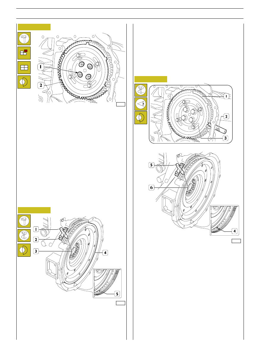
Figure 60
When the adjustment with the slots (1) is not enough to make
up the phase difference and the camshaft turns because it
becomes integral with the gear (2); as a result, the reference
value of the cam lift varies, in this situation it is necessary to
proceed as follows:
1) lock the screws (2, Figure 59) and turn the engine flywheel
clockwise by approx. 1/2 turn;
2) turn the engine flywheel anticlockwise until the dial gauge
gives a reading of the lift of the cam of the camshaft of 4.44
±0.05 mm;
3) take out the screws (2, Figure 59) and remove the gear (1)
from the camshaft.
Turn the flywheel (4) again to bring about the following
conditions:
- a notch (5) can be seen through the inspection window;
- the tool 99360612 (1) inserted to the bottom of the seat
of the engine speed sensor (2) and (3).
77260
Phonic wheel timing
Turn the crankshaft by taking the piston of cylinder no. 1 into
the compression phase at T.D.C.; turn the flywheel in the
opposite direction to the normal direction of rotation by
approximately 1/4 of a turn.
Again turn the flywheel in its normal direction of rotation until
you see the hole marked with the double notch (4) through
the inspection hole under the flywheel housing. Insert tool
99360612 (5) into the seat of the flywheel sensor (6).
Insert the tool 99360613 (2), via the seat of the phase sensor,
onto the tooth obtained on the phonic wheel.
Should inserting the tool (2) prove difficult, loosen the screws
(3) and adjust the phonic wheel (1) appropriately so that the
tool (2) gets positioned on the tooth correctly. Go ahead and
tighten the screws (3).
Mount the gear (2) Figure 60 with the 4 slots (1) centred with
the fixing holes of the camshaft, locking the relevant screws to
the required tightening torque.
Check the timing of the shaft by first turning the flywheel
clockwise to discharge the cylinder completely and then turn
the flywheel anticlockwise until the dial gauge gives a reading
of 4.44
±0.05.
Check the timing conditions described in Figure 58.
Figure 61
Figure 62