Engine Iveco C10/C13/C78/Cursor 13/Cursor 78. Manual - part 69
73535
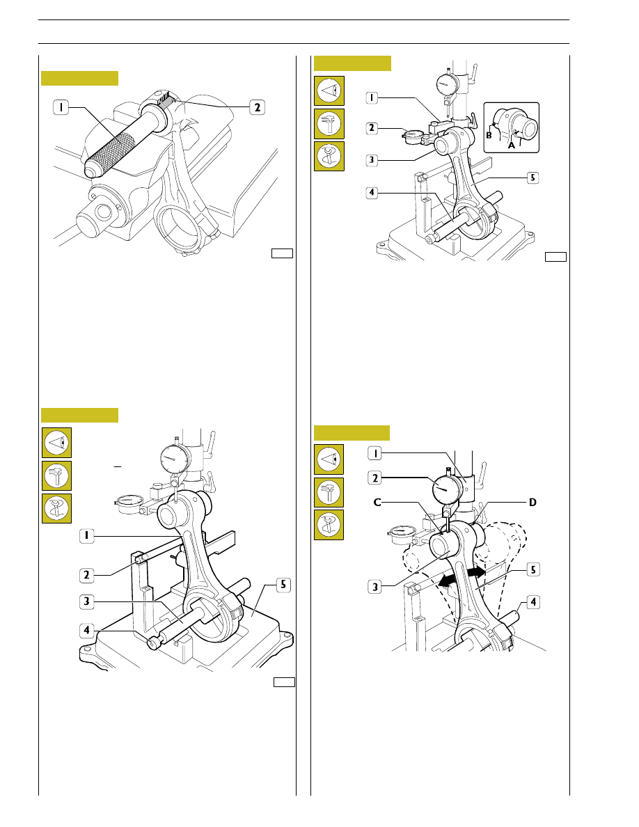
Figure 62
Figure 63
Check the bushing in the small end has not come loose and
shows no sign of scoring or seizure; replace it if it does.
The bushing (2) is removed and fitted with a suitable drift (1).
When driving it in, make absolutely sure that the holes for the
oil to pass through in the bushing and small end coincide.
Using a boring machine, rebore the bushing so as to obtain
a diameter of 50.019 — 50.035.
Checking connecting rods
61696
Checking axis alignment
Check the alignment of the axes of the connecting rods (1)
with device 99395363 (5), proceeding as follows:
Fit the connecting rod (1) on the spindle of the tool
99395363 (5) and lock it with the screw (4).
Set the spindle (3) on the V-prisms, resting the connecting
rod (1) on the stop bar (2).
Check the torsion of the connecting rod (5) by comparing
two points (A and B) of the pin (3) on the horizontal plane
of the axis of the connecting rod.
Position the mount (1) of the dial gauge (2) so that this
pre-loads by approx. 0.5 mm on the pin (3) at point A and
zero the dial gauge (2). Shift the spindle (4) with the
connecting rod (5) and compare any deviation on the
opposite side B of the pin (3): the difference between A and
B must be no greater than 0.08 mm.
Figure 64
61694
Check the bending of the connecting rod (5) by comparing
two points C and D of the pin (3) on the vertical plane of the
axis of the connecting rod.
Position the vertical mount (1) of the dial gauge (2) so that
this rests on the pin (3) at point C.
Swing the connecting rod backwards and forwards seeking
the highest position of the pin and in this condition zero the
dial gauge (2).
Shift the spindle (4) with the connecting rod (5) and repeat
the check on the highest point on the opposite side D of the
pin (3). The difference between point C and point D must be
no greater than 0.08 mm.
Figure 65
Checking bending
Bushings
34
SECTION 4 - OVERHAUL AND TECHNICAL SPECIFICATIONS