Engine Iveco C10/C13/C78/Cursor 13/Cursor 78. Manual - part 41


  Index      Iveco     Engine Iveco C10/C13/C78/Cursor 13/Cursor 78 - service repair manual 2006 year


Search            


Content   ..  39  40  41  42   ..


Engine Iveco C10/C13/C78/Cursor 13/Cursor 78. Manual - part 41


The oil pressure control valve is located on the left-hand side
of the crankcase.
Start of opening pressure 5 bars.

73542

73543

Figure 12

Figure 13

Figure 14

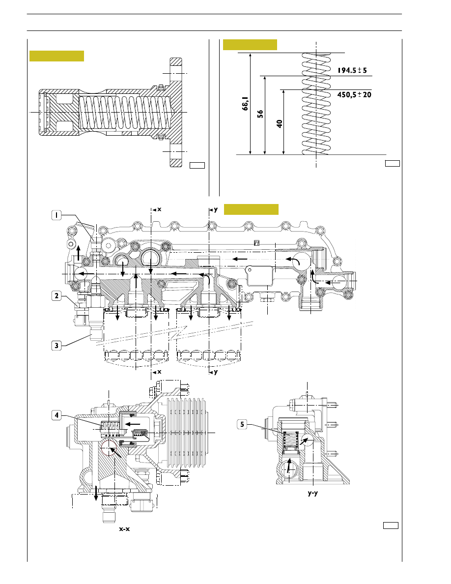
MAIN DATA TO CHECK THE OIL PRESSURE

CONTROL VALVE SPRING

HEAT EXCHANGER

The heat exchanger is fitted with: 1. Oil temperature sensor - 2. Oil pressure sensor for pressure gauge - 3. Transmitter for

low pressure warning lamp - 4. Heat valve - 5. By-pass valve. Number of elements 9.

Oil pressure control valve

Heat exchanger for engine versions with

double filter

78950

14

SECTION 1 - GENERAL SPECIFICATIONS

HEAT EXCHANGER

The following elements are fitted on the intercooler: 1. Transmitter for low pressure warning lamp - 2. By-pass valve -

3. Oil temperature sensor - 4. Oil pressure sensor for single gauge - 5. Heat valve. Number of intercooler elements: 7.

Heat exchanger for engine versions with single filter

77818

Figure 15

SECTION 1 - GENERAL SPECIFICATIONS

15

This is a new generation of filters that permit much more
thorough filtration as they are able to holder back a greater
amount of particles of smaller dimensions than those held
back by conventional filters with a paper filtering element.

These high-filtration devices, to date used only in industrial
processes, make it possible to:

- reduce the wear of engine components over time;

- maintain the performance/specifications of the oil and

thereby lengthen the time intervals between changes.

External spiral winding
The filtering elements are closely wound by a spiral so that
each fold is firmly anchored to the spiral with respect to the
others. This produces a uniform use of the element even in
the worst conditions such as cold starting with fluids with a
high viscosity and peaks of flow. In addition, it ensures uni-
form distribution of the flow over the entire length of the
filtering element, with consequent optimization of the loss of
load and of its working life.

Mount upstream
To optimize flow distribution and the rigidity of the filtering el-
ement, this has an exclusive mount composed of a strong mesh
made of nylon and an extremely strong synthetic material.

Filtering element
Composed of inert inorganic fibres bound with an exclusive
resin to a structure with graded holes, the element is manu-
factured exclusively to precise procedures and strict quality
control.

Mount downstream
A mount for the filtering element and a strong nylon mesh
make it even stronger, which is especially helpful during cold
starts and long periods of use. The performance of the filter
remains constant and reliable throughout its working life and
from one element to another, irrespective of the changes in
working conditions.

Structural parts
The o-rings equipping the filtering element ensure a perfect
seal between it and the container, eliminating by-pass risks
and keeping filter performance constant. Strong corrosion-
proof bottoms and a sturdy internal metal core complete the
structure of the filtering element.

When mounting the filters, keep to the following rules:

- Oil and fit new seals.

- Screw down the filters to bring the seals into contact

with the supporting bases.

- Tighten the filter to a torque of 35-40 Nm.

73545

47447

73546

Figure 16

Figure 17

Figure 18

The valve quickly opens at a pressure of: 3 bars.

Thermostatic valve

Start of opening:
- travel 0.1 mm at a temperature of 82

±2°C

.

End of opening:
- travel 8 mm at a temperature of 97

°C

.

Engine oil filters

By-pass valve

16

SECTION 1 - GENERAL SPECIFICATIONS

COOLING

Description

The engine cooling system is of the closed-circuit, forced circulation type.
It consists mainly of the following components:

- expansion tank, not supplied (by IVECO);

- a heat exchanger to cool down lubrication oil;

- a water pump with centrifugal system incorporated in the cylinder block;

- fan, not supplied;

- a 2-way thermostat controlling the coolant circulation.

Operation

The water pump is actuated by the crankshaft through a poli-V belt and sends coolant to the cylinder block, especially to the
cylinder head (bigger quantity). When the coolant temperature reaches and overcomes the operating temperature, the
thermostat is opened and from here the coolant flows into the radiator and is cooled down by the fan.
The pressure inside the system, due to temperature change, is adequately controlled through the expansion vessel.

SECTION 1 - GENERAL SPECIFICATIONS

17


Content   ..  39  40  41  42   ..