Engine Iveco C10/C13/C78/Cursor 13/Cursor 78. Manual - part 7


  Index      Iveco     Engine Iveco C10/C13/C78/Cursor 13/Cursor 78 - service repair manual 2006 year


Search            


Content   ..  5  6  7  8   ..


Engine Iveco C10/C13/C78/Cursor 13/Cursor 78. Manual - part 7


Injection phase
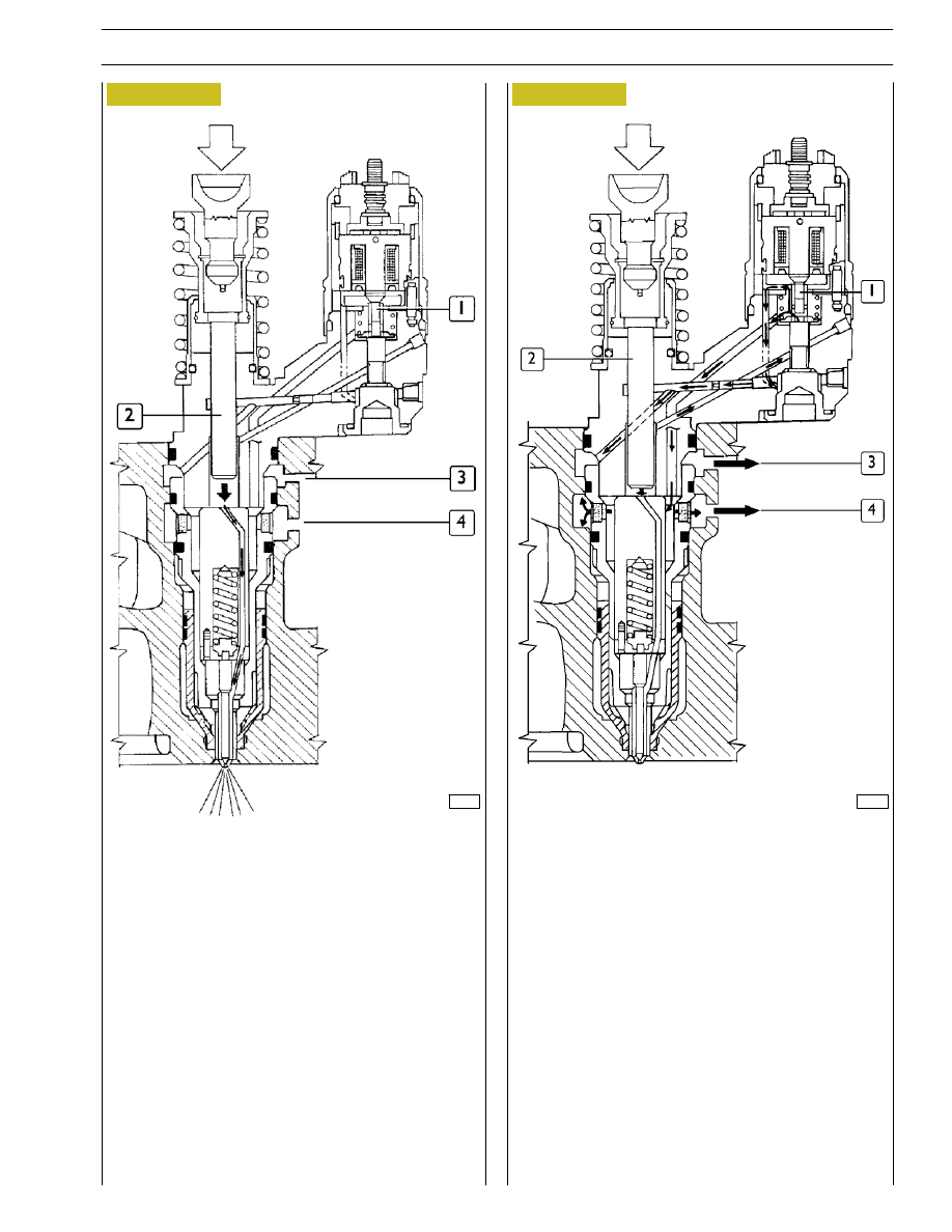
The injection phase begins when, at a certain point in the
down phase of the pumping element, the solenoid valve gets
energized and the fuel valve (1) shuts.

The moment delivery begins, appropriately calculated by the
electronic control unit, depends on the working conditions
of the engine.

The cam continues with the rocker arm to push the pumping
element (2) and the injection phase continues as long as the
fuel valve (1) stays shut.

1. Fuel valve - 2. Pumping element - 3. Fuel outlet -

4. Filling and backflow passage.

1. Fuel valve - 2. Pumping element - 3. Fuel outlet -

4. Filling and backflow passage.

60670

Figure 9

60671

Figure 10

Pressure Reduction phase
Injection ceases when the fuel valve (1) opens, at a certain
point in the down stroke of the pumping element, after the
solenoid valve gets de-energized.

The fuel flows back through the open valve (1), the injector
holes and the passage (4) into the cylinder head.

The time for which the solenoid valve stays energized,
appropriately calculated by the electronic control unit, is the
duration of injection (delivery) and it depends on the working
conditions of the engine.

SECTION 2 - FUEL

7

SECTION 3 - INDUSTRIAL APPLICATION

1

SECTION 3

Industrial application

Page

CLEARANCE DATA

3

. . . . . . . . . . . . . . . . . . . . .

PART ONE - MECHANICAL COMPONENTS

5

ENGINE ASSEMBLY DISASSEMBLY

7

. . . . . . . . .

ASSEMBLING THE ENGINE ON THE BENCH

14

.

ENGINE FLYWHEEL

16

. . . . . . . . . . . . . . . . . . . . .

- Fitting engine flywheel

16

. . . . . . . . . . . . . . . . . . .

- Fitting camshaft

17

. . . . . . . . . . . . . . . . . . . . . . . .

- Fitting pump-injectors

18

. . . . . . . . . . . . . . . . . . .

- Fitting rocker-arm shaft assembly

18

. . . . . . . . . .

- Camshaft timing

19

. . . . . . . . . . . . . . . . . . . . . . .

- Phonic wheel timing

21

. . . . . . . . . . . . . . . . . . . .

- Intake and exhaust rocker play adjustment and

pre-loading of rockers controlling pump injectors

22

ENGINE COMPLETION

23

. . . . . . . . . . . . . . . . . .

PART TWO -

ELECTRICAL EQUIPMENT

29

. . . . . . . . . . . . .

- Components on the engine F2B

31

. . . . . . . . . . .

BLOCK DIAGRAM

32

. . . . . . . . . . . . . . . . . . . . . . .

- EDC MS 6.2 electronic control unit

33

. . . . . . . .

- EDC control unit PIN-OUT

34

. . . . . . . . . . . . . .

- Connector “A” (Engine)

34

. . . . . . . . . . . . . . . . .

- EDC control unit PIN-OUT

35

. . . . . . . . . . . . . .

- Connector “B” (Frame area)

35

. . . . . . . . . . . . . .

- Engine coolant temperature sensor

37

. . . . . . . .

- Fuel temperature sensor

38

. . . . . . . . . . . . . . . . .

- Pulse transmitter

39

. . . . . . . . . . . . . . . . . . . . . . .

2

SECTION 3 - INDUSTRIAL APPLICATION

Page

- Distribution pulse transmitter

40

. . . . . . . . . . . . .

- Boosting pressure transmitter

41

. . . . . . . . . . . . .

- Air temperature transmitter on manifold

42

. . . . .

PRE/POST-HEATING RESISTANCE

43

. . . . . . . . . .

EDC SYSTEM FUNCTIONS

44

. . . . . . . . . . . . . . . .

PART THREE - TROUBLESHOOTING

47

. . . . . .

PREFACE

49

. . . . . . . . . . . . . . . . . . . . . . . . . . . . . . .

PART FOUR -

MAINTENANCE PLANNING

57

. . . . . . . . . . .

MAINTENANCE PLANNING

59

. . . . . . . . . . . . . .

- Recovery

59

. . . . . . . . . . . . . . . . . . . . . . . . . . . . .

- Inspection and/or maintenance interventions

59

.

- Checks not included in maintenance

planning-daily checks

60

. . . . . . . . . . . . . . . . . . . .

MAINTENANCE PROCEDURES

60

. . . . . . . . . . . .

- Checks and controls

60

. . . . . . . . . . . . . . . . . . . .

Data, features and performances are valid only if the setter fully complies with all the installation prescriptions provided
by Iveco Motors.

Furthermore, the users assembled by the setter shall always be in conformance to couple, power and number of turns
based on which the engine has been designed.

NOTE

SECTION 3 - INDUSTRIAL APPLICATION

3

CLEARANCE DATA

Type

F2BE0684

F2B0687

Type

A*B001

A*B002

A*B101

ρ

Compression ratio

16

± 0.8

16

± 0.8

16

± 0.8

Max. output

kW
(HP)
rpm

265

(360)

2100

265

(360)

2100

220

(300)

2200

Max. torque

Nm
(kgm)
rpm

1420

(142)

1500

1420

(142)

1500

1250

(125)

1200

Loadless engine
idling

rpm

1300

1300

900

Loadless engine
peak

rpm

2110

2110

2430

Bore x stroke

mm

Displacement

cm

3

115 x 125

7790

115 x 125

7790

115 x 125

7790

SUPERCHARGING

Turbocharger type

Intercooler

Direct injection

HX40W

bar

LUBRICATION

Oil pressure
(warm engine)

- idling

bar

- peak rpm

bar

Forced by gear pump, relief valve single action

oil filter

4
5

COOLING
Water pump control
Thermostat
- start of opening ºC

Liquid

Through belt

85


Content   ..  5  6  7  8   ..