Engine Iveco C10/C13/C78/Cursor 13/Cursor 78. Manual - part 5
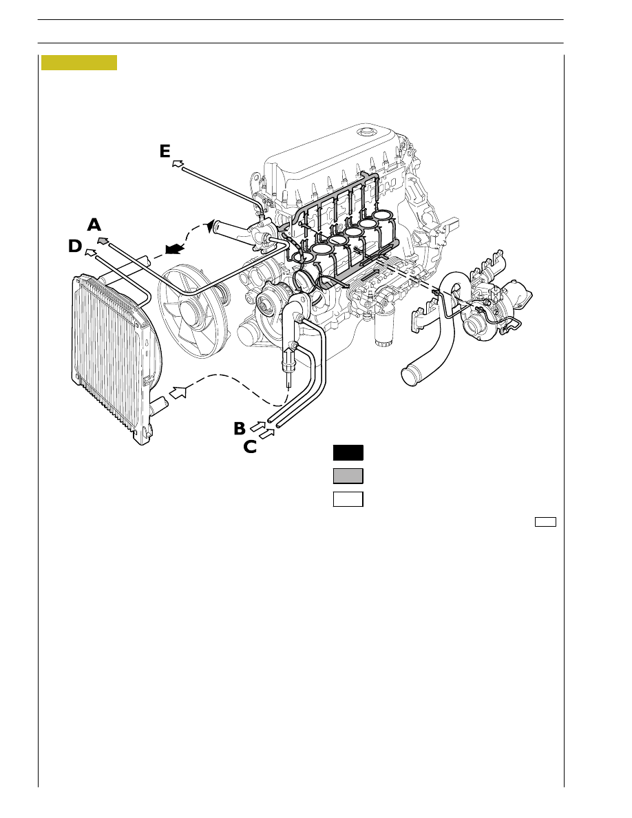
Figure 16
99248
A/B
outlet/inlet for vehicle heater
C
inlet from the expansion vessel
D/E
outlet from the radiator and the thermostat body for expansion vessel inlet
Water flowing out of the thermostat
Water circulating in the engine
Water flowing into the pump
16
SECTION 1 - GENERAL SPECIFICATIONS