Isuzu Amigo / Axiom / Trooper / Rodeo / VehiCross. Manual - part 973


  Index      Isuzu     Isuzu Amigo / Axiom / Trooper / Rodeo / VehiCross - service repair manual 1999-2002 year


Search            


Content   ..  971  972  973  974   ..


Isuzu Amigo / Axiom / Trooper / Rodeo / VehiCross. Manual - part 973


8C–2

ENTERTAINMENT

Cigarette Lighter

General Description

When the cigarette lighter is pushed in with the starter
switch at either “ACC” or “ON” position, a circuit is formed
in the cigarette lighter case to heat the lighter coil.
The cigarette lighter is sprung back to its original position
after the lighter coil is heated.

Removal

1. Disconnect the battery ground cable.
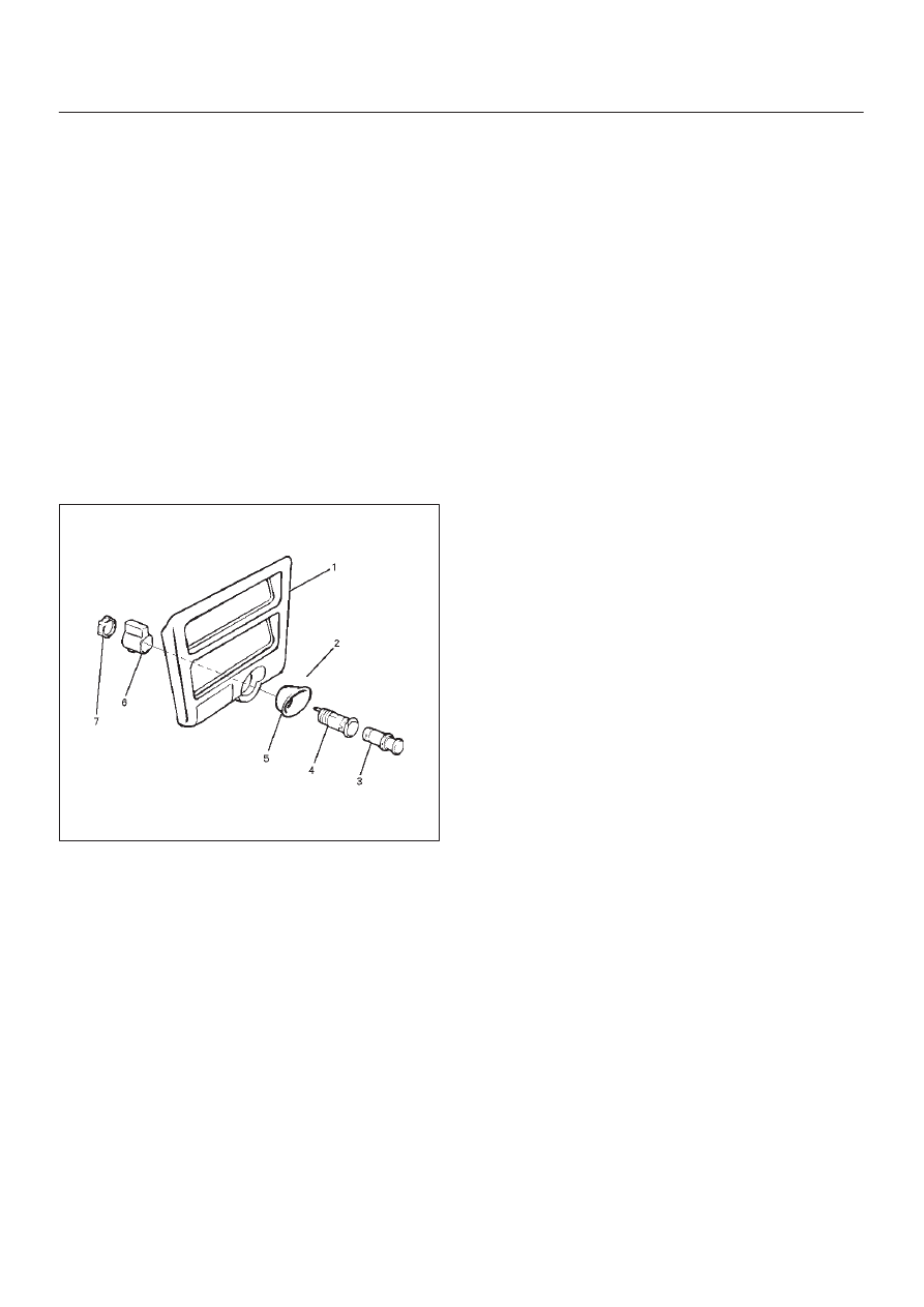
2. Remove the lower cluster assembly(1).

Refer to the Instrument Panel Assembly removal
steps in Body Structure section.

3. Disconnect the connectors, remove the socket of the

illumination light, the retaining ring(7), the outer
case(6), the cigarette lighter(3) and socket(4), the
bezel(5) and then remove the cigarette lighter
assembly(2).

 826RS007

Installation

To install, follow the removal steps in the reverse order,
noting the following point.

1. When installing the bezel, align the projected portion

of the socket with the notch of the bezel.

ENTERTAINMENT

8C–3

Digital Clock and Outside Temp

Removal

1. Disconnect the battery ground cable.
2. Remove the front console assembly(1).

Refer to the Instrument Panel Assembly in Body
Structure section.

3. Remove the lower cluster assembly(2).

Refer to the Instrument Panel Assembly in Body
Structure section.

4. Remove the instrument panel driver lower cover

assembly(3).
Refer to the Instrument Panel Assembly in Body
Structure section.

740R200050

5. Remove the instrument panel cluster assembly(4).

Refer to the Instrument Panel Assembly in Body
Structure section.

6. Disconnect the connector and push the lock from the

back side of the instrument panel cluster assembly to
remove the digital clock and outside temp (5).

821R200035

Installation

To install, follow the removal steps in the reverse order,
noting the following point.

1. Push in the switch with your fingers until it locks

securely.

8C–4

ENTERTAINMENT

Front ACC Socket

Removal

1. Disconnect the battery ground cable.
2. Remove the front cover assembly (1).

Refer to the “Instrument Panel Assembly” in the Body
Structure section of this manual.

3. Disconnect the connectors (2).
4. Twist the ACC cover (3) counterclockwise to remove

it together with the ACC socket (4).

826R200029

Installation

To install, follow the removal steps in the reverse order,
noting the following point.

1. The projection portion socket is united with Bezel

cutting and lacking, and is attached.

Rear ACC Socket

Removal

1. Disconnect the battery ground cable.
2. Remove two screws and disconnect the connector to

remove the ACC socket (1).

810RW311

Installation

To install, follow the removal steps in the reverse order.

ENTERTAINMENT

8C–5

Rod Type Antenna

Removal

1. Disconnect the battery ground cable.
2. Turn the antenna rod(1) counterclockwise to remove

it.

3. Remove three screws and nine clips to remove the

fender inner liner(2).

4. Disconnect the feeder cable connector at the inside of

the vehicle, remove the housing bracket screw, turn
the lock nut counterclockwise to remove it together
with the base mold and then remove the housing(3).

890RS004

Installation

To install, follow the removal steps in the reverse order.


Content   ..  971  972  973  974   ..