Isuzu Amigo / Axiom / Trooper / Rodeo / VehiCross. Manual - part 968


  Index      Isuzu     Isuzu Amigo / Axiom / Trooper / Rodeo / VehiCross - service repair manual 1999-2002 year


Search            


Content   ..  966  967  968  969   ..


Isuzu Amigo / Axiom / Trooper / Rodeo / VehiCross. Manual - part 968


8A–18

LIGHTING SYSTEM

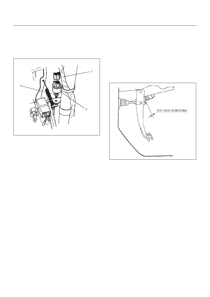
Brake Switch (W/Cruise Control)

Removal

1. Disconnect the battery ground cable.
2. Disconnect the connector(1), loosen the lock nut(3)

and then remove the brake switch(2) by turning it.

310RW010

Installation

To install, follow the removal steps in the reverse order,
noting the following points.

1. Check to see if the brake pedal has been returned by

the return spring to the specified position.

2. Turn the switch clockwise until the tip of the threaded

portion of the brake switch contacts the pedal arm.

3. Turn the switch counterclockwise until the space

between the tip of the threaded portion and the pedal
arm is 0.5 to 1.0 mm (0.02 – 0.04 in.).

310RS003

Turn Signal Switch/Cornering Light Switch (Combination Switch)

Removal and Installation

Refer to the removal and installation steps of the Lighting
Switch (Combination Switch) in this section.

LIGHTING SYSTEM

8A–19

Hazard Warning Switch

Removal

1. Disconnect the battery ground cable.
2. Remove the front console assembly(1).

Refer to the Instrument Panel Assembly in Body
Structure section.

3. Remove the lower cluster assembly(2).

Refer to the Instrument Panel Assembly in Body
Structure section.

4. Remove the instrument panel driver lower cover

assembly(3).
Refer to the Instrument Panel Assembly in Body
Structure section.

740R200050

5. Remove the instrument panel cluster assembly(4).

Refer to the Instrument Panel Assembly in Body
Structure section.

6. Disconnect the connector and push the lock from the

back side of the instrument panel cluster assembly to
remove the hazard warning switch(5).

825RW024

Installation

To install, follow the removal steps in the reverse order,
noting the following point.

1. Push in the switch with your fingers until it locks

securely. 

8A–20

LIGHTING SYSTEM

Tailgate Switch

Removal

1. Disconnect the battery ground cable.
2. Remove the screw and disconnect the connector(1)

to remove the tailgate switch(2).

683RS014

Installation

To install, follow the removal steps in the reverse order.

Door Switch

Removal

1. Disconnect the battery ground cable.
2. Remove the screw and disconnect the connector to

remove the door switch(1).

825RS043

Installation

To install, follow the removal steps in the reverse order.

LIGHTING SYSTEM

8A–21

Rear Defogger Switch

Removal

1. Disconnect the battery ground cable.
2. Remove the front console assembly(1). 

Refer to the Instrument Panel Assembly in Body
Structure section.

3. Remove the lower cluster assembly(2). 

Refer to the Instrument Panel Assembly in Body
Structure section.

4. Remove the instrument panel driver lower cover

assembly(3). 
Refer to the Instrument Panel Assembly in Body
Structure section.

740R200050

5. Remove the instrument panel cluster assembly(4). 

Refer to the Instrument Panel Assembly in Body
Structure section.

6. Disconnect the connector and push the lock from the

back side of the instrument panel cluster assembly to
remove the rear defogger switch(5). 

825RW023

Installation 

To install, follow the removal steps in the reverse order,
noting the following point.

1. Push in the switch with your fingers until it locks

securely. 


Content   ..  966  967  968  969   ..