Isuzu Amigo / Axiom / Trooper / Rodeo / VehiCross. Manual - part 967
8A–14
LIGHTING SYSTEM
Starter Switch
Removal
1. Disconnect the battery ground cable.
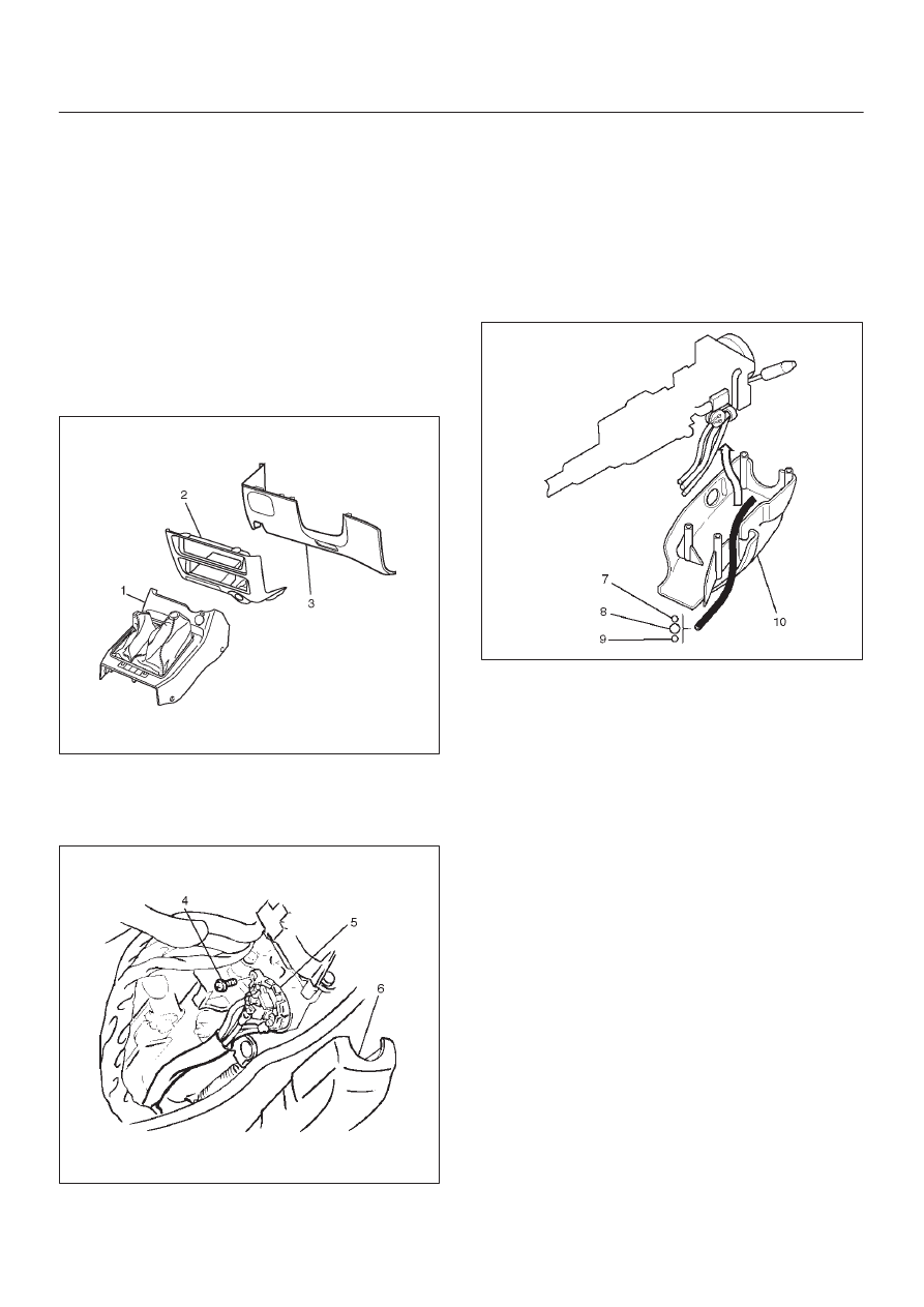
2. Remove the front console assembly(1).
Refer to Instrument Panel Assembly in Body
Structure section.
3. Remove the lower cluster assembly(2).
Refer to the Instrument Panel Assembly in Body
Structure section.
4. Remove the instrument panel driver lower cover
assembly(3).
Refer to the Instrument Panel Assembly in Body
Structure section.
740R200050
5. Remove seven screws to remove the steering
cowl(6).
6. Disconnect the connector, remove the screw(4) and
then remove the starter switch(5).
431RW005
Installation
To install, follow the removal steps in the reverse order
noting the following point.
1. When installing the steering cowl(10), be sure to pass
the harnesses through the route as shown in the
figure so that the starter switch harness(7), the
combination switch harness(8) and the inflator
module harness(9) will not get caught.
431RW008