Isuzu Amigo / Axiom / Trooper / Rodeo / VehiCross. Manual - part 904


  Index      Isuzu     Isuzu Amigo / Axiom / Trooper / Rodeo / VehiCross - service repair manual 1999-2002 year


Search            


Content   ..  902  903  904  905   ..


Isuzu Amigo / Axiom / Trooper / Rodeo / VehiCross. Manual - part 904


7A–42

AUTOMATIC TRANSMISSION (4L30–E)

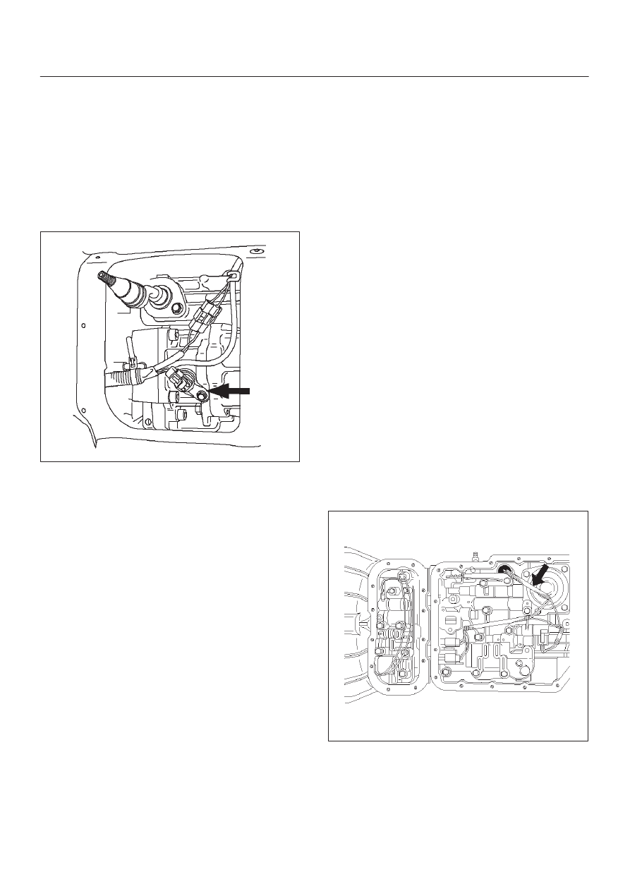
Speed Sensor (Extension Housing)

Removal

1. Disconnect  battery ground cable.
2. Remove front console.
3. Remove selector lever assembly.
4. Disconnect speed sensor harness connector from

speed sensor.

5. Remove one 10 mm screw and speed sensor with

O–ring.

241RW007

Installation

1. Inspect the speed sensor O–ring, and replace it if

necessary.

2. Install speed sensor assembly and 10 mm screw.

Torque: 9 N

m (78 lb in)

3. Connect speed sensor harness connector to speed

sensor.

4. Install selector lever assembly.

D

Adjust shift lock cable. Refer to Selector Lever in
this section.

5. Install front console.
6. Connect  battery ground cable.

Transmission Oil Temperature Sensor (Main Case)

Removal

1. Raise the vehicle and support it on jack stands.
2. Disconnect battery ground cable.
3. Drain fluid.
4. Remove sixteen 10 mm main case oil pan fixing

screws, main case oil pan, and gasket.

5. Disconnect wiring harness from shift solenoids, band

apply solenoid,  and 7 way connector of main case.
Pull only on connectors, not on wiring harness.

6. Remove wiring harness assembly with transmission

oil temperature sensor.

244RY001

Installation

1. Install wiring harness assembly with transmission oil

temperature sensor to band apply solenoid, shift
solenoids, and 7 way connector of main case.

7A–43

AUTOMATIC TRANSMISSION (4L30–E)

2. Install oil pan gasket, oil pan, and sixteen 10 mm

fixing screws. Tighten the screws to the specified
torque.

Torque: 11 N

m (96 lb in)

3. Fill transmission through the overfill screw hole of oil

pan, using ATF DEXRON

–III.

Refer to Changing Transmission Fluid in this section.

4. Connect battery ground cable.

Front Oil Seal (Converter Housing)

Removal

1. Remove transmission assembly with transfer case

from the vehicle. Refer to Transmission (With
Transfer Case / Extension Assembly) in this section.

2. Remove torque converter from converter housing.
3. Remove three screws and oil seal ring from converter

housing.

241RW008

Installation

1. Apply clean ATF to the new oil seal ring lip.

D

Install oil seal ring to converter housing. Tighten the
screws to the specified torque.

Torque: 3 N

m (26 lb in)

2. Install torque converter to converter housing.
3. Install transmission assembly with transfer case

(4

×

4) / extension assembly (4

×

2) to the vehicle. Refer

to Transmission (With Transfer Case / Extension
Assembly) in this section.

Rear Oil Seal (Extension Housing)

Removal

1. Remove transfer case assembly (4

×

4) or extension

assembly (4

×

2) from the vehicle. Refer to Transfer

Case in Drive Line/Axle section.

2. Remove rear oil seal from transmission extension

housing.

241RW005

7A–44

AUTOMATIC TRANSMISSION (4L30–E)

Installation

1. Use J–36797 extension housing oil seal installer, and

install the rear oil seal  to the transmission extension
housing.

2. Install the transfer case assembly (4

×

4) or extension

assembly (4

×

2) to the vehicle. Refer to Transfer Case

in Drive Line/Axle section.

Transmission (4L30–E)

Disassembly

NOTE: During the disassembly and reassembly, perform
the following:

D

Wash each part thoroughly, and blow air through each
oil passage and groove to eliminate blockage.

D

Seal rings, roll pins, and gaskets should be replaced.

D

When assembling the components, apply
DEXRON

–III Automatic Transmission Fluid (ATF)

to each seal, rotating part, and sliding part.

D

Do not dip part facings, such as  clutch or brake drive
plates, in cleaner when washing it.
Also, always coat parts with new ATF two or three
times after cleaning with solvent.

1. Remove torque converter (1). 

D

Drain fluid from torque converter.

D

Attach J–8763–02 holding fixture to the
transmission and set it on J–3289–20 holding
fixture base.

NOTE: Do not overtighten the tool, as case damage may
result.

420RW021

2. Remove O–ring (2) from turbine shaft.
3. Remove two 10mm mode switch screws, selector

lever nut, cover, and mode switch (3).

4. Remove twelve 10mm adapter case oil pan (4) fixing

screws, adapter oil pan, and gasket.

5. Disconnect electrical wiring connections (5) from

solenoids and 4 way connector of adapter case. Pull
on connectors only, not on wiring harness.

6. Remove seven 13mm adapter case valve body (6)

fixing screws, adapter case valve body assembly,
transfer plate, and two gaskets.

D

Remove wiring harness and 4 way connector.

7. Remove sixteen 10mm main case oil pan (7) fixing

screws, main oil pan, magnet, and gasket.

8. Remove three 13mm oil filter (8) fixing screws and oil

filter.

9. Remove two 13mm manual detent (9) fixing screws,

roller and spring, and manual detent.

10. Disconnect wiring harness assembly (10) from band

apply solenoid, shift solenoids, and main case 7 way
connector.
Pull on connectors only, not on wiring harness.

11. Remove four 13mm servo cover (11) fixing screws,

servo cover, and gasket.

12. Remove seven 13mm valve body screws and ground

wire from main case.

D

Remove wiring harness assembly (5) from the
adapter case side.

D

Remove main valve body assembly (12) with
manual valve link and transfer plate. Note the
position of the link (long end into valve, short end
into range selector lever).

D

Remove 7 way connector.

D

Remove gasket transfer plate from main case.

7A–45

AUTOMATIC TRANSMISSION (4L30–E)

13. Remove two check balls (13) from main case.

240RY001

14. Turn transmission to vertical position to drain fluid.

Return back to horizontal position when drained.

D

Install J–23075 servo piston spring compressor
with offset to the rear of case.

D

Compress servo piston assembly.

D

Remove servo piston retaining ring (14).

D

Slowly release servo piston assembly (15).

D

Remove tool.


Content   ..  902  903  904  905   ..