Isuzu Amigo / Axiom / Trooper / Rodeo / VehiCross. Manual - part 721


  Index      Isuzu     Isuzu Amigo / Axiom / Trooper / Rodeo / VehiCross - service repair manual 1999-2002 year


Search            


Content   ..  719  720  721  722   ..


Isuzu Amigo / Axiom / Trooper / Rodeo / VehiCross. Manual - part 721


6A–65

ENGINE MECHANICAL

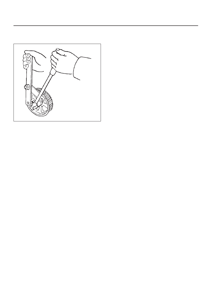
5. Tighten bolt for camshaft drive gear pulley to the

specified torque using the J–43041 universal holder.

Torque: 98 N·m (72 lb ft)

014RW060

6A–66

ENGINE MECHANICAL

Crankshaft

Crankshaft and Associated Parts

013RW009

Legend

(1) Cylinder Head Assembly
(2) Crankcase with Oil Pan
(3) Oil Pipe and O-Ring
(4) Oil Strainer and O-Ring
(5) Oil Pump Assembly
(6) Cylinder Block Side  Bolts
(7) Oil Gallery

(8) Piston and Connecting Rod Assembly
(9) Flywheel

(10) Rear Oil Seal Retainer and Oil Seal

(11) Main Bearing Cap

(12) Crankshaft
(13) Main Bearing Cap Fixing Bolts
(14) Oil Gallery Fixing Bolts

6A–67

ENGINE MECHANICAL

Disassembly

1. Remove cylinder head assembly (1). Refer to

“Cylinder Head” in this manual.

2. Remove crankcase with oil pan (2). Refer to “Oil Pan

and Crankcase” in this manual.

CAUTION: Take care not to damage or deform the
sealing flange surface of crankcase.

3. Remove oil pipe and O-ring (3).
4. Remove oil strainer and O-ring (4).
5. Remove oil pump assembly (5).
6. Remove crankcase side bolts (6).
7. Remove oil gallery (7).
8. Remove piston and connecting rod assembly (8).

Refer to “Piston, Piston Ring and Connecting Rod” in
this manual.

9. Remove flywheel (9).

10. Remove rear oil seal retainer (10).

11. Remove main bearing cap (11).

12. Remove crankshaft (12).

Inspection and Repair

1. Crankshaft

Set the dial indicator as shown in the illustration and
measure the crankshaft thrust clearance. If the thrust
clearance exceeds the specified limit, replace the
thrust bearings as a set.

Thrust Clearance
Standard : 0.06 mm–0.24 mm

(0.0024 in–0.0094 in)

Limit : 0.30 mm (0.0118 in)

015RS003

Main Bearing Clearance

1. Remove the bearing caps and measure the oil

clearance.

2. Remove the main bearing cap fixing bolts in the

sequence shown in the illustration.
Arrange the removed main bearing caps in the
cylinder number order.
Remove the main bearings.

015RS004

3. Remove the crankshaft.

Remove the main bearings.

4. Clean the upper and lower bearings as well as the

crankshaft main journal.

5. Check the bearings for damage or excessive wear.

The bearings must be replaced as a set if damage or
excessive wear is discovered during inspection.

6. Set the upper bearings and the thrust washers to their

original positions.
Carefully install the crankshaft.

7. Set the lower bearings to the bearing cap original

position.

8. Apply plastigage to the crankshaft journal unit as

shown in the illustration.

NOTE: Do not set the plastigage on the oil hole.

015RS005

6A–68

ENGINE MECHANICAL

9. Install main bearing caps, oil gallery and crank case

bolts in the order shown, and tighten each bolt to the
specified torque.

NOTE: Do not apply engine oil to the crank case side
bolts.

Main bearing cap bolts.
Torque: 39 N·m (29lb ft)

Oil gallery fixing bolts.
Torque:
1st step: 29 N·m (21 lb ft)
2nd step 55

°∼

 65

°

Crank case side bolts
Torque : 39 N·m (29lb ft)

NOTE: Do not allow the crankshaft to rotate.

015RS006

10. Remove the main bearing caps in the sequence

shown in the illustration.

015RS004

11. Measure the plastigage width and determine the oil

clearance. If the oil clearance exceeds the specified
limit, replace the main bearings as a set and/or
replace the crankshaft.

Standard : 0.019 mm–0.043 mm

(0.0007 in–0.0017 in)

Limit : 0.08 mm (0.0031 in)

015RS008

12. Clean the plastigage from the bearings and the

crankshaft.
Remove the crankshaft and the bearings.

Crankshaft (12) Inspection

Inspect the surface of the crankshaft journal and crank
pins for excessive wear and damage. Inspect the oil seal
fitting surfaces for excessive wear and damage. Inspect
the oil ports for obstructions.

Inspection and Repair

1. Carefully set the crankshaft on the V–blocks. Slowly

rotate the crankshaft and measure the runout. If the
crankshaft runout exceeds the specified limit, the
crankshaft must be replaced.

Runout : 0.04 mm (0.0016 in)

015RS007


Content   ..  719  720  721  722   ..