Isuzu Amigo / Axiom / Trooper / Rodeo / VehiCross. Manual - part 720


  Index      Isuzu     Isuzu Amigo / Axiom / Trooper / Rodeo / VehiCross - service repair manual 1999-2002 year


Search            


Content   ..  718  719  720  721   ..


Isuzu Amigo / Axiom / Trooper / Rodeo / VehiCross. Manual - part 720


6A–61

ENGINE MECHANICAL

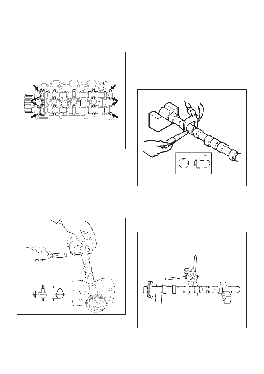
2. Remove twenty fixing bolts from inlet and exhaust

camshaft bearing cap on one side bank, then
camshaft bearing cap (2).

014RW027

3. Remove camshaft assembly (3), (4).
4. Remove three fixing bolts (7) from camshaft drive

gear retainer (8), then camshaft drive gear assembly.

Inspection and Repair

1. Use a micrometer to measure the cam lobe height

and uneven wear. Replace the camshaft if either the
lobe height or the uneven wear exceeds the specified
limit.

Lobe height : 44.709 mm (1.7602 in)
Uneven wear : 0.05 mm (0.0020 in)

014RW043

2. Use a micrometer to measure the diameter and the

uneven wear of the camshaft journals.
Replace the camshaft if the diameter or the uneven
wear exceeds the specified limit.

Journal Diameter
Standard : 25.972 mm–25.993 mm

(1.0225 in–1.0233 in)

Limit : 25.8 mm (1.0157 in)
Uneven wear : 0.05 mm (0.0020 in)

014RS023

3. Place the camshaft on V–blocks.

Slowly rotate the camshaft and measure the runout
with a dial indicator.
Replace the camshaft if the runout exceeds the
specified limit.

Runout
Limit : 0.1 mm (0.0039 in)

014RW044

6A–62

ENGINE MECHANICAL

4. Measure the camshaft journal oil clearance.

1. Measure the camshaft bearing cap housing

inside diameter.

NOTE: Tighten camshaft bearing cap (2) to specified
torque before measuring the camshaft bearing cap inside
diameter.

Torque : 10 N·m (87 lb in)

014RW031

2. Subtract the camshaft outside diameter from the

camshaft bearing cap housing inside diameter.

Oil Clearance
Standard : 0.027 mm–0.078 mm

(0.0011 in–0.0031 in)

Limit : 0.11 mm (0.0043 in)

014RW037

5. Replace the cylinder head and/or camshaft if the

measured oil clearance exceeds the specified limit.
1. Carefully clean the camshaft journal, the

camshaft bracket, and the cylinder head.

2. Install camshaft assembly and camshaft bearing

cap (2), tighten twenty bolts (1) on one side bank
to the specified torque.

Torque: 10 N·m (87 lb in)

014RW031

3. Measure the camshaft thrust clearance with a dial

indicator. Replace the camshaft and/or the
cylinder head if the camshaft thrust clearance
exceeds the specified limit.

Camshaft thrust Clearance
Standard : 0.03 mm–0.08 mm

(0.0012 in.–0.0031 in.)

Limit : 0.12 mm (0.0047 mm)

014RW035

6A–63

ENGINE MECHANICAL

Reassembly

1. Install camshaft drive gear assembly and tighten

three bolts to specified torque.

Torque: 10 N·m (87 lb in)

2. Tighten sub gear setting bolt.

1. Use J–42686 to turn sub gear to right direction

until the M5 bolt hole aligns between camshaft
driven gear and sub gear.

2. Tighten M5 bolt suitable torque for prevent

moving the sub gear.

014RW041

3. Install camshaft assembly and camshaft bearing

caps, tighten twenty bolts on one side bank to the
specified torque.
1. Apply engine oil to camshaft journal and bearing

surface of camshaft bearing cap.

2. Align timing mark on intake camshaft (one dot for

right bank, two dots for left bank) and exhaust
camshaft (one dot for right bank, two dots for left
bank) to timing mark on camshaft drive gear (one
dot).

014RW020

Legend

(1) Intake Camshaft Timing Gear for Right Bank
(2) Intake Camshaft Timing Gear for Left Bank
(3) Exhaust Camshaft Timing Gear
(4) Discerning Mark

LI: Left Bank Intake

RI: Right Bank Intake

LE: Left Bank Exhaust

RE: Right Bank Exhaust

014RW023

Legend

(1) Right Bank Camshaft Drive Gear
(2) Left Bank Camshaft Drive Gear
(3) Timing Mark on Drive Gear
(4) Dowel Pin

6A–64

ENGINE MECHANICAL

014RW024

Legend

(1) Right Bank
(2) Left Bank

(3) Alignment Mark on Camshaft Drive Gear
(4) Alignment Mark on Camshaft
(5) Alignment Mark on Retainer

3. Tighten twenty bolts in numerical order on one

side bank as shown in the illustration.

Torque: 10 N·m (87 lb in)

014RW031

4. If the oil seal requires replacement, use the J–42985

to install the oil seal.

014RW034


Content   ..  718  719  720  721   ..