Isuzu Amigo / Axiom / Trooper / Rodeo / VehiCross. Manual - part 719


  Index      Isuzu     Isuzu Amigo / Axiom / Trooper / Rodeo / VehiCross - service repair manual 1999-2002 year


Search            


Content   ..  717  718  719  720   ..


Isuzu Amigo / Axiom / Trooper / Rodeo / VehiCross. Manual - part 719


6A–57

ENGINE MECHANICAL

7. Check that the valve seat insert surface is in contact

with the entire circumference of the valve.

014RS014

Valve Seat Insert Replacement

1. Arc weld the rod at several points. Be careful not to

damage the aluminum section.

2. Allow the rod to cool for a few minutes. This will cause

the valve seat to shrink.

3. Strike the rod and pull it out.

014RS015

4. Carefully clean the valve seat press–fit section on the

cylinder head side.

5. Heat the press–fit section with steam or some other

means to cause expansion. Cool the valve seat with
dry ice or some other means.

6. Insert the press–fit section into the valve seat

horizontally.

Standard fitting interference: 0.14 mm–0.09 mm
(0.0055 in–0.0035 in)

7. After insertion, use a seat grinder to grind finish the

seating face. Carefully note the seating angle, the
contact width, and the depression.

8. Lap the valve and the seat.
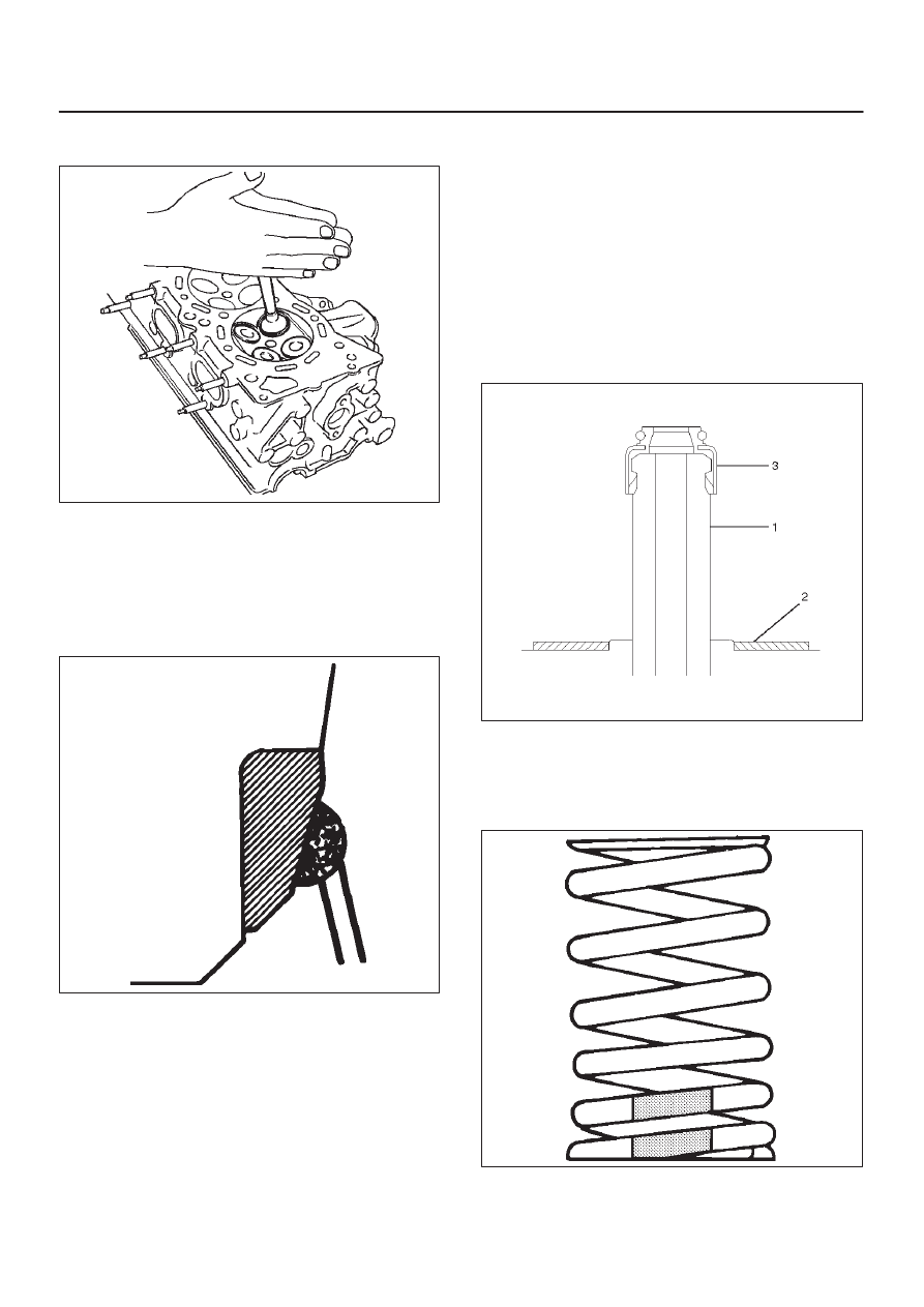
Reassembly

1. Install valve guide (1) to cylinder head. Apply engine

oil to the outside of the valve guide. Using valve guide
replacer J–42899, drive in a new valve guide from the
camshaft side.

2. Install oil controller (3) and spring lower seat (2).

Using oil controller replacer J–37281, drive in a new
oil controller.

014RW058

3. Install valve to valve guide. Before install valve guide

apply engine oil to the outside of the valve stem.

4. Install valve spring to cylinder head. Attach the valve

spring to the lower spring seat. The painted area of
the valve spring should be facing downward.

014RS020

6A–58

ENGINE MECHANICAL

5. Install lower valve spring seat, valve spring and upper

valve spring seat then put split collars on the upper
spring seat, using the J–8062 valve spring
compressor and J–42898 valve spring compressor
adapter to install the split collars.

014RW042

6. Install tappet with shim.
7. Install camshaft assembly.

D

Refer to installation procedure for Camshaft in this
manual.

Valve Clearance Adjustments

NOTE: To adjust valve clearance, apply engine oil to the
cam as well as to the adjusting shim (2) with the cylinder
head built on the cylinder block, give a few turns to the
camshaft by means of timing pulley tightening bolt, and
measure valve clearance when the nose of cam is just
opposite to maximum cam lift (1) as shown in illistration
below.

014RW081

Legend

(1) Cam
(2) Shim
(3) Tappet

Valve Clearance Standard Value (cold)

Intake: 0.23 mm–0.33 mm

(0.0091 in–0.0130 in)

Exhaust: 0.25 mm–0.35 mm

(0.0098 in–0.0138 in)

Selection of Adjusting Shim

Shim to be selected = (Thickness of removed shim) +
(Valve clearance measurement – Standard valve)
Based on the above formula, the best suited shim should
be selected from 41 sorts of shim (differently thick at
0.02mm (0.0008 in) intervals from 2.40mm (0.0945 in)
through 3.2mm (0.1260 in) thick). Install the shim and
check valve clearance.

6A–59

ENGINE MECHANICAL

Replacement of Shim

Let the cam push down the edge of tappet by using
J–42689 valve clearance adjusting tool and push out the
shim with a flat blade screw driver as shown in illustrations
below.

014RW082

014RW083

014RW084

6A–60

ENGINE MECHANICAL

Camshaft

Camshaft and Associated Parts

014RW040

Legend

(1) Camshaft Bearing Cap Fixing Bolt
(2) Camshaft Bearing Cap
(3) Camshaft Assembly Intake
(4) Camshaft Assembly Exhaust
(5) Pulley Fixing Bolt

(6) Camshaft Drive Gear Pulley
(7) Retainer Fixing Bolt
(8) Retainer
(9) Camshaft Drive Gear

(10) Oil Seal

Disassembly

1. Remove fixing bolt (5) for camshaft drive gear pulley

using the J–43041 universal holder.

014RW060


Content   ..  717  718  719  720   ..