Isuzu Amigo / Axiom / Trooper / Rodeo / VehiCross. Manual - part 648


  Index      Isuzu     Isuzu Amigo / Axiom / Trooper / Rodeo / VehiCross - service repair manual 1999-2002 year


Search            


Content   ..  646  647  648  649   ..


Isuzu Amigo / Axiom / Trooper / Rodeo / VehiCross. Manual - part 648


4C–18

DRIVE SHAFT SYSTEM

Front Drive Shaft Joint

Front Drive Shaft Joints Replace-
ment

D

Refer to Front Drive Axle Assembly Replacement in
this section, and refer to Front Hub and Disc in
Suspension section.

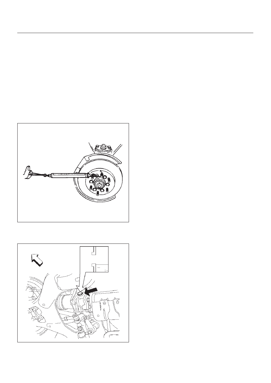
Front Hub Bearing Preload Check

Check the hub bearing preload at the wheel pin.

New bearing and new oil seal:

19.6 – 24.5 N (4.4 – 5.5 lb)

Used bearing and new oil seal: 

11.8– 17.7  N (2.6 – 4.0 lb)

411RS001

Inspection Of Shift On The Fly System
Gear Oil

412RT002

1. Open filler plug and make sure that the oil is up to the

plug port.
If the level oil is low, replenish with gear oil GL–5
grade.

2. Tighten the filler plug to specified torque.

Torque: 78 N·m (58 lb in)

4C–19

DRIVE SHAFT SYSTEM

Front Axle Drive Shaft

Front Axle Drive Shaft and Associated Parts

412RW003

Legend

(1) Axle Case and  Differential
(2) DOJ Case Assembly
(3) Snap Ring
(4) Bearing
(5) Snap Ring
(6) Oil Seal
(7) Bracket
(8) DOJ Case
(9) Circlip

(10) Bolt

(11) Drive Shaft Joint Assembly

(12) Snap Ring

(13) Spacer
(14) Ball
(15) Snap Ring
(16) Ball Retainer
(17) Ball Guide
(18) Band
(19) Bellows
(20) Band
(21) Band
(22) Bellows
(23) Band
(24) BJ Shaft
(25) Dust Seal

4C–20

DRIVE SHAFT SYSTEM

Disassembly

NOTE: For the left side, follow the same steps as right
side.

1. Raise the hooked end of the band (1) with a

screwdriver or equivalent.

412RS009

2. Remove band.
3. Pry off circlip (1) with a screwdriver or equivalent.

412RS010

4. Remove drive shaft joint assembly.
5. Using snap ring pliers, remove the snap ring.

412RS011

6. Remove spacer.
7. Remove the six balls (1) with a screwdriver or

equivalent.

412RS012

4C–21

DRIVE SHAFT SYSTEM

8. Using snap ring pliers, remove the snap ring (1)

fastening the ball retainer to the center shaft.

412RS013

9. Remove ball retainer, ball guide and bellows.

10. Raise the hooked end of the band (1) with a

screwdriver or equivalent.

412RS014

11. Remove band.

12. Remove bellows.
13. Remove dust seal.
14. Remove BJ shaft assembly.
15. Remove the mounting bracket fixing bolts, and then

remove DOJ case assembly  from the axle case.

16. Remove snap ring and bearing.
17. Remove snap ring and oil seal.
18. Remove bracket.

Inspection and Repair

Make necessary correction or parts replacement if wear,
damage, corrosion or any other abnormal conditions are
found through inspection.
Check the following parts:

1. Drive shaft joint assembly
2. DOJ case, ball, ball guide, ball retainer
3. Bellows
4. Bearing
5. Dust seal, oil seal

Bushing Replacement

D

Remove the bushings using a remover J–39378–1
and hammer.

412RS015

D

By using installer J–39378–2 and base J–39378–3,
press fit the bushings into the bracket.

412RS016


Content   ..  646  647  648  649   ..