Isuzu Amigo / Axiom / Trooper / Rodeo / VehiCross. Manual - part 579
POWER ASSISTED SYSTEM
2A–45
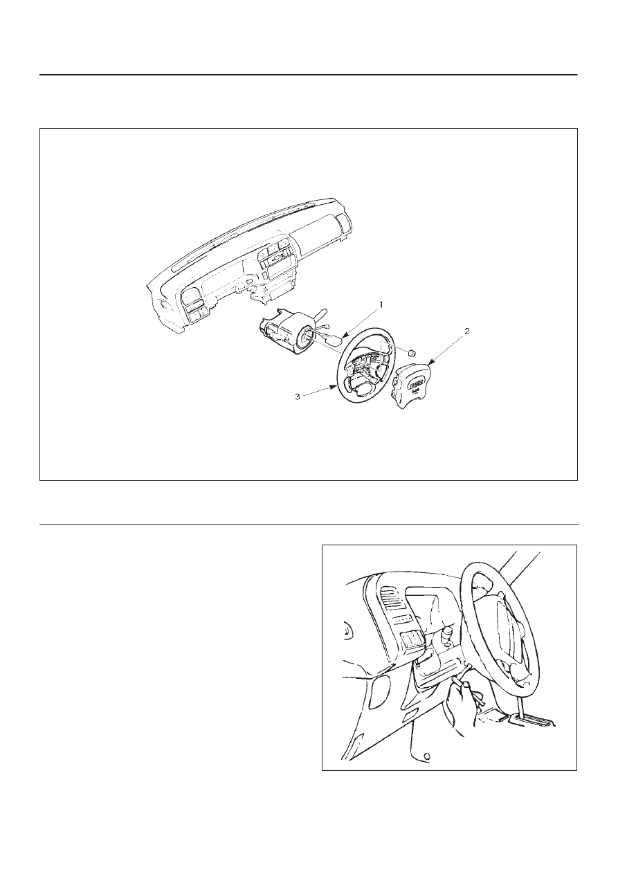
Inflator Module
Inflator Module and Associated Parts
827RS048
Legend
(1) Module Connector
(2) Inflator Module
(3) Steering Wheel
Removal
1. Turn the steering wheel so that the vehicle’s wheels
are pointing straight ahead.
2. Turn the ignition switch to “LOCK”.
3. Disconnect the battery “–” terminal cable, and wait at
least 5 minutes.
4. Disconnect the yellow 2-way SRS connector located
under the steering column.
5. Loosen the inflator module fixing bolt from behind the
steering wheel assembly using a TORX
driver or
equivalent until the inflator module can be released
from steering assembly .
827RT008