Isuzu Amigo / Axiom / Trooper / Rodeo / VehiCross. Manual - part 577


  Index      Isuzu     Isuzu Amigo / Axiom / Trooper / Rodeo / VehiCross - service repair manual 1999-2002 year


Search            


Content   ..  575  576  577  578   ..


Isuzu Amigo / Axiom / Trooper / Rodeo / VehiCross. Manual - part 577


POWER ASSISTED SYSTEM

2A–37

Removal

1. Remove wheel and tire assembly.  Refer to Wheel

Replacement in Suspension section.

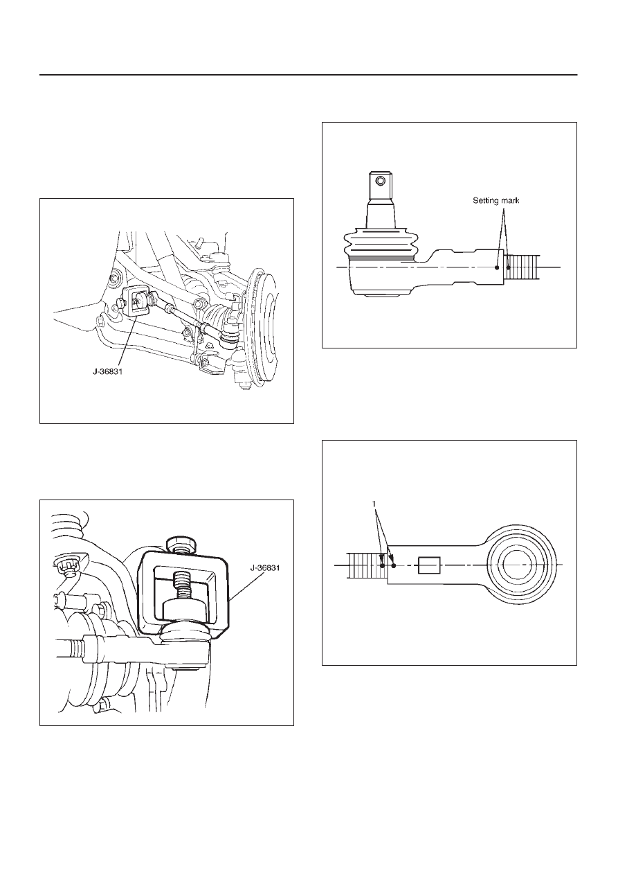
2. Remove nut and cotter pin, then use  remover

J–36831 to disconnect outer track rod assembly at
the center track rod.

CAUTION: Be careful not to damage the ball joint
boot.

433RS009

3. Remove nut and cotter pin then use remover J–36831

to remove outer track rod assembly from the knuckle
arm.

CAUTION: Be careful not to damage the ball joint
boot.

433RS013

4. Remove outer lock nut.

5. Apply setting marks (1) to ensure reassembly of the

parts in their original position, then remove  outer rod
end assembly.

433RS014

6. Remove inner lock nut.

NOTE: For either outer rod, the screw on the right side of
the vehicle is threaded counterclockwise. 

7. Apply setting marks (1) to ensure reassembly of the

parts in their original position, then remove inner rod
end.

433RS015

Inspection and Repair

Make necessary correction or parts replacement if wear,
damage, corrosion, bending, deteriorations or any other
abnormal condition are found through inspection.
Check the following parts:

D

Rod end assembly

D

Ball joint (Boot, screws and tapered surfaces) 

2A-38

POWER ASSISTED SYSTEM

Installation

1. Install inner rod end and align the setting marks

applied during disassembly. 

2. Tighten the inner lock nut to specified torque.

Torque: 118 N·m (87 lb ft)

NOTE: For either outer rod, the screw on the right side of
the vehicle is threaded counterclockwise.

3. Install outer rod end assembly and align the setting

marks applied during disassembly. 

4. Tighten the  outer lock nut to specified torque.

Torque: 118 N·m (87 lb ft)

5. Install knuckle arm nut and cotter pin then tighten the

nut to the specified torque, with just enough additional
torque to align cotter pin holes. Install new cotter pin.

Torque: 98 N·m (72 lb ft)

6. Install center track rod and nut and cotter pin then

tighten the nut to the specified torque, with just
enough additional torque to align cotter pin holes.
Install new cotter pin.

Torque: 98 N·m (72 lb ft)

NOTE: If replacing the track rod, adjust the new track rod
length.

Rod length: 328.3 mm (12.93 in)

433RS016

NOTE: Adjust the toe-in. Refer to Front End Alignment
Inspection and Adjustment
 in this section.

POWER ASSISTED SYSTEM

2A–39

Relay Lever

Relay Lever and Associated Parts

433RS017

Legend

(1) Bolt and Nut
(2) Relay Lever and Bracket
(3) Bracket

(4) Relay Lever
(5) Nut and Washer
(6) Nut and Cotter Pin

Removal

1. Raise the vehicle and support the frame with suitable

safety stands.

2. Remove nut and cotter pin then use remover J–36831

to disconnect relay lever at the center track rod.

433RS011

2A-40

POWER ASSISTED SYSTEM

3. Remove stabilizer bar bolt and nut and push the

stabilizer bar aside, then remove the relay lever bolts
and nuts.

433RS018

4. Remove relay lever and bracket.
5. Remove relay lever nut and washer.
6. Remove relay lever, use remover J–22912–01 to

remove relay lever from the bracket.

433RS019

7. Remove bracket.

Installation

1. Install bracket. 
2. Install relay lever. 
3. Install nut and washer and tighten the nut to the

specified torque.

Torque: 118 N·m (87 lb ft)

4. Install relay lever and bracket. 
5. Install bolt and nut and tighten it to the specified

torque.

Torque: 44 N·m (33 lb ft)

6. Install nut and cotter pin and tighten the nut to the

specified torque, with just enough additional torque to
align cotter pin holes. Install new cotter pin.

Torque: 59 N·m (43 lb ft)


Content   ..  575  576  577  578   ..