Isuzu Amigo / Axiom / Trooper / Rodeo / VehiCross. Manual - part 580
POWER ASSISTED SYSTEM
2A–49
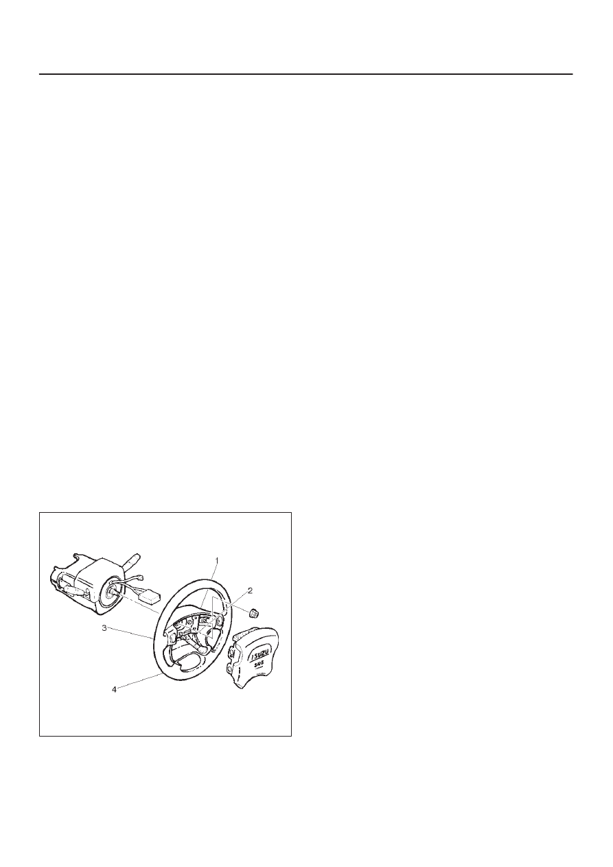
Installation
1. Install steering wheel by aligning the setting marks
made when removing.
CAUTION: Never apply force to the steering wheel
in direction of the shaft by using a hammer or other
impact tools in an attempt to remove the steering
wheel. The steering shaft is designed as an energy
absorbing unit.
2. Tighten the steering wheel fixing nut to the specified
torque.
Torque: 34 N·m (25 lb ft)
3. Connect horn lead.
4. Support the module and carefully connect the module
connector.
CAUTION:
D
Never use the air bag assembly from another
vehicle. Use only the air bag assembly for “UX”.
D
The driver’s air bag assembly (Inflator module)
for 1999 model has different characteristic to the
parts for 1998 model.When replace the driver’s
air bag assembly, confirm the parts number and
use only the parts for 1999 model. (The driver’s
air bag assembly for 1999 model has “yellow” bar
codes label. 1998 model has “white” bar codes
label.)
NOTE: Pass the lead wire through the tabs on the plastic
cover (wire protector) of inflator to prevent lead wire from
being pinches.
D
Secure the module with one bolt to relieve weight on
the wire connector.
D
Tighten bolts to specified sequence as illustrated.
Torque: 8 N·m (69 lb in)
827RW003
5. Connect the yellow 2-way SRS connector located
under the steering column.
6. Connect the battery “–” terminal cable.
7. Turn the ignition switch to “ON” while watching
warning light. Light should flash 7 times and then go
off. If lamp does not operate correctly, refer to
Restraints section.