Isuzu Amigo / Axiom / Trooper / Rodeo / VehiCross. Manual - part 500
EXTERIOR/INTERIOR TRIM
8J–19
Roof Moulding
Parts Location
660R200003
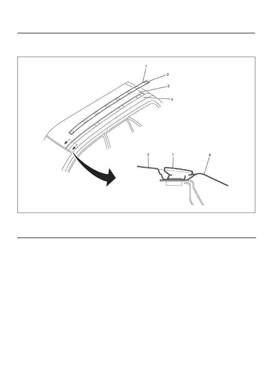
Legend
(1) Roof Moulding Assembly
(2) Clips
(3) Roof Panel
(4) Body Side Outer Panel
Removal
1. Remove the roof moulding.
D
Pry the roof moulding covers with the nine clip
positions from the roof panel.
Installation
To install, follow the removal steps in the reverse order.