Isuzu Amigo / Axiom / Trooper / Rodeo / VehiCross. Manual - part 490


  Index      Isuzu     Isuzu Amigo / Axiom / Trooper / Rodeo / VehiCross - service repair manual 1999-2002 year


Search            


Content   ..  488  489  490  491   ..


Isuzu Amigo / Axiom / Trooper / Rodeo / VehiCross. Manual - part 490


SECURITY AND LOCKS

8H–7

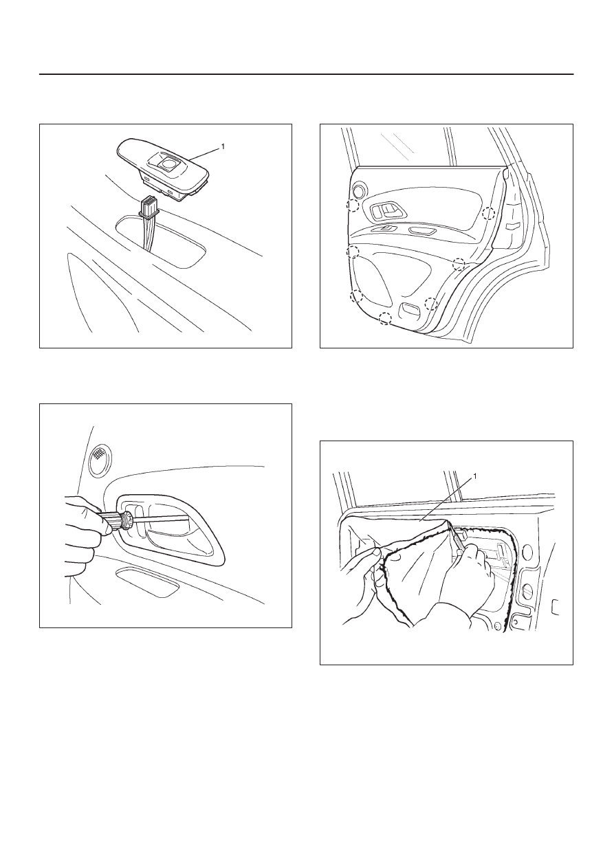
3. Remove the power window switch (1).

D

Pry the power window switch and remove the
connector.

655R200004

4. Remove the inside handle.

D

Open the screw cover and remove the screw.

D

Disconnect the cable.

655R200008

5. Pull the trim panel at the 7 clip positions.

D

Disconnect the tweeter and courtesy light
connectors.

655R200005

6. Remove the pull box bracket.
7. Remove the inside lock bracket.

D

Disconnect the cable.

8. Peel the waterproof sheet.

D

Taking notice of the door harness, peel the
waterproof sheet off the door panel carefully.

651R200004

8H–8

SECURITY AND LOCKS

9. Remove the door lock assembly.

D

Disconnect the locking link and harness connector.

D

Remove the 3 fixing Torx screws and bolt.

652R200001

Installation

To install, follow the removal steps in the reverse order,
noting the following points.

1. Apply chassis grease to the lock assembly and striker

moving surface.

2. Tighten the door lock assembly fixing screws to the

specified torque.

Torque 7 N·m (61 Ib in)

3. Check that the door lock operates smoothly.

SECURITY AND LOCKS

8H–9

Rear Outside Handle

Rear Outside Handle and Associated Parts

655R200007

Legend

(1) Outside Handle
(2) Door Lock Assembly
(3) Pull Box Bracket
(4) Pull Box

(5) Door Trim Panel
(6) Power Window Switch
(7) Inside Handle
(8) Inside Lock Bracket
(9) Waterproof Sheet

Removal

1. Disconnect the battery ground cable.
2. Remove the door trim panel.

D

Refer to 

Rear Door Lock Assembly in this section.

3. Peel the waterproof sheet.

D

Taking notice of the door harness, peel the
waterproof sheet off the door panel carefully.

4. Disconnect the locking link and remove fixing bolts to

remove the outside handle.

Installation

To install, follow the removal steps in the reverse order,
noting the following points.

1. Check that the outside handle operates smoothly.
2. Tighten the outside handle fixing bolts to the specified

torque.

Torque 7 N·m (61 Ib in)

8H–10 SECURITY AND LOCKS

Tailgate Lock and Outside Handle

Tailgate Lock, Outside Handle and Associated Parts

681R200008

Legend

(1) Tailgate Panel Assembly
(2) Tailgate Lower Trim Cover
(3) Tailgate Pull Box

(4) Clip
(5) Tailgate Lock Assembly
(6) Locking Link
(7) Tailgate Outside Handle

Removal

1. Disconnect the battery ground cable.
2. Remove the tailgate pull box.
3. Remove the three clips.
4. Remove the tailgate lower trim cover.

D

Pull the tailgate lower trim cover at the thirteen clip
positions.

5. Remove the tailgate lock assembly.

D

Remove the three fixing bolts.

D

Disconnect the locking links and harness
connector.

6. Remove the tailgate outside handle.

D

Remove the two fixing nuts.

7. Remove the tailgate lock cylinder(2).

D

Remove the fixing clip(3) pull lock cylinder from the
outside handle (1).

681R200005


Content   ..  488  489  490  491   ..