Isuzu Amigo / Axiom / Trooper / Rodeo / VehiCross. Manual - part 410


  Index      Isuzu     Isuzu Amigo / Axiom / Trooper / Rodeo / VehiCross - service repair manual 1999-2002 year


Search            


Content   ..  408  409  410  411   ..


Isuzu Amigo / Axiom / Trooper / Rodeo / VehiCross. Manual - part 410


7A–53

AUTOMATIC TRANSMISSION (4L30–E)

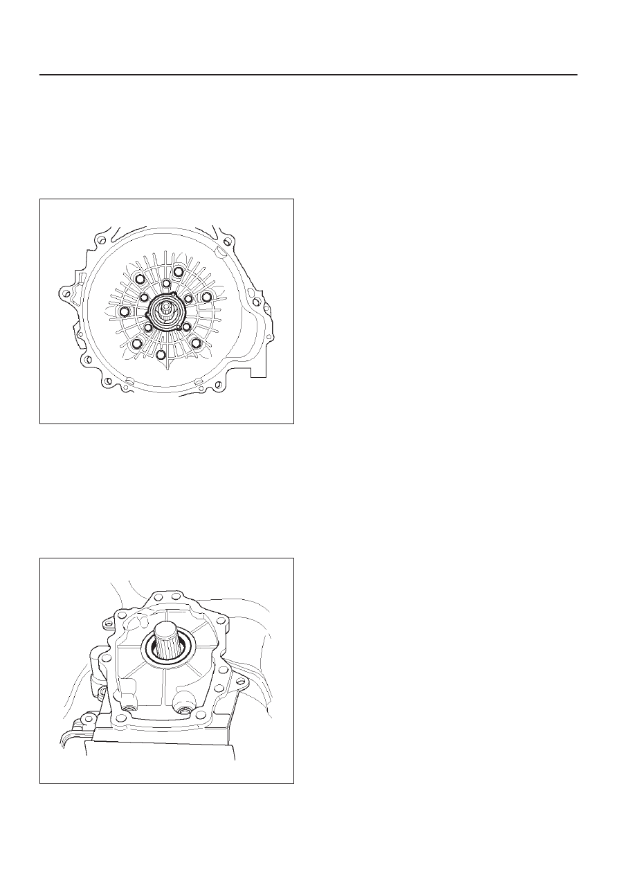
Front Oil Seal (Converter Housing)

Removal

1. Remove transmission assembly from the vehicle.

Refer to 

Transmission Assembly in this section.

2. Remove torque converter from converter housing.
3. Remove three screws and oil seal ring from converter

housing.

241RW008

Installation

1. Apply clean ATF to the new oil seal ring lip.

D

Install oil seal ring to converter housing. Tighten the
screws to the specified torque.

Torque: 3 N

m (26 lb in)

2. Install torque converter to converter housing.
3. Install transmission assembly to the vehicle. Refer to

Transmission Assembly in this section.

Rear Oil Seal (Extension Assembly)

Removal

1. Remove transfer case assembly (4

×

4) or extension

assembly (4

×

2) from the vehicle. Refer to 

Transfer

Case in Drive Line/Axle section (4

×

4).

2. Remove rear oil seal from transmission extension

assembly.

241RW005

Installation

1. Use J–36797 extension assembly oil seal installer,

and install the rear oil seal  to the transmission
extension assembly.

2. Install the transfer case assembly (4

×

4) or extension

assembly (4

×

2) to the vehicle. Refer to 

Transfer Case

in Drive Line/Axle section (4

×

4).

7A–54

AUTOMATIC TRANSMISSION (4L30–E)

Transmission (4L30–E)

Disassembly

NOTE: During the disassembly and reassembly, perform
the following:

D

Wash each part thoroughly, and blow air through each
oil passage and groove to eliminate blockage.

D

Seal rings, roll pins, and gaskets should be replaced.

D

When assembling the components, apply
DEXRON

–III Automatic Transmission Fluid (ATF)

to each seal, rotating part, and sliding part.

D

Do not dip part facings, such as  clutch or brake drive
plates, in cleaner when washing it.
Also, always coat parts with new ATF two or three
times after cleaning with solvent.

1. Remove torque converter (1). 

D

Drain fluid from torque converter.

D

Attach J–8763–02 holding fixture to the
transmission and set it on J–3289–20 holding
fixture base.

NOTE: Do not overtighten the tool, as case damage may
result.

420RW021

2. Remove O–ring (2) from turbine shaft.
3. Remove two 10mm mode switch screws, selector

lever nut, cover, and mode switch (3).

4. Remove twelve 10mm adapter case oil pan (4) fixing

screws, adapter oil pan, and gasket.

5. Disconnect electrical wiring connections (5) from

solenoids and 4 way connector of adapter case. Pull
on connectors only, not on wiring harness.

6. Remove seven 13mm adapter case valve body (6)

fixing screws, adapter case valve body assembly,
transfer plate, and two gaskets.

D

Remove wiring harness and 4 way connector.

7. Remove sixteen 10mm main case oil pan (7) fixing

screws, main oil pan, magnet, and gasket.

8. Remove three 13mm oil filter (8) fixing screws and oil

filter.

9. Remove two 13mm manual detent (9) fixing screws,

roller and spring, and manual detent.

10. Disconnect wiring harness assembly (10) from band

apply solenoid, shift solenoids, and main case 7 way
connector.
Pull on connectors only, not on wiring harness.

11. Remove four 13mm servo cover (11) fixing screws,

servo cover, and gasket.

12. Remove seven 13mm valve body screws from main

case.

D

Remove wiring harness assembly (5) from the
adapter case side.

D

Remove main valve body assembly (12) with
manual valve link and transfer plate. Note the
position of the link (long end into valve, short end
into range selector lever).

D

Remove 7 way connector.

D

Remove gasket transfer plate from main case.

7A–55

AUTOMATIC TRANSMISSION (4L30–E)

13. Remove two check balls (13) from main case.

240RY001

14. Turn transmission to vertical position to drain fluid.

Return back to horizontal position when drained.

D

Install J–23075 servo piston spring compressor
with offset to the rear of case.

D

Compress servo piston assembly.

D

Remove servo piston retaining ring (14).

D

Slowly release servo piston assembly (15).

D

Remove tool.

7A–56

AUTOMATIC TRANSMISSION (4L30–E)

15. Remove servo piston assembly (15), return spring

(16), and servo apply rod (17).

242RS002

16. Rotate transmission to horizontal position, pan side

down.

D

Remove one 10mm screw, and speed sensor (18)
with “O” ring.

17. Remove seven 8mm extension housing hexagon

socket head screws, extension housing assembly
(19), and gasket.

18. Remove retaining ring (20). (4

×

4)

NOTE: Use extra long, needle- nose pliers.

D

Remove flange nut (20). (4

×

4)

D

Remove flange and O–ring (20). (4

×

2)

19. Remove speed wheel (21).
20. Remove wheel parking lock (with seal ring) (22).

241RW012

21. Rotate transmission to vertical position, converter

housing up.

D

Loosen the converter housing and oil pump
assembly fixing screws, but do not remove the five
13 mm inner screws if oil pump disassembly is
required.

D

Remove seven outer screws.

D

Remove converter housing and oil pump assembly
(23).

22. Remove gasket (24).


Content   ..  408  409  410  411   ..