Isuzu Amigo / Axiom / Trooper / Rodeo / VehiCross. Manual - part 408


  Index      Isuzu     Isuzu Amigo / Axiom / Trooper / Rodeo / VehiCross - service repair manual 1999-2002 year


Search            


Content   ..  406  407  408  409   ..


Isuzu Amigo / Axiom / Trooper / Rodeo / VehiCross. Manual - part 408


7A–45

AUTOMATIC TRANSMISSION (4L30–E)

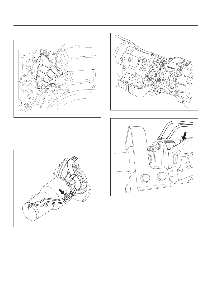
12. Install harness heat protector.

Torque: 6 N

m (52 lb in)

815RW002

13. Connect transmission harness connector and clip.

Connector : Adapter case, mode switch, main case,
magnetic sensor, transfer connectors (4

×

4) and car

speed sensor.

14. Connect fuel pipe bracket to transmission side.

NOTE: See “NOTE” of removal steps.

141R200003

(4

×

4)

240R200010

(4

×

2)

141R200002

7A–46

AUTOMATIC TRANSMISSION (4L30–E)

15. Install fuel pipe heat protector and clip.
16. Connector fuel pipe bracket to third crossmember.

141RW004

17. Install center exhaust pipe (4

×

4).

Torque: 43 N

m (32 lb ft)

18. Install front propeller shaft (4

×

4) and rear propeller

shaft.

Torque: 63 N

m (46 lb ft)

19. Install transfer protector (4

×

4) and fairing plate.

Torque (transfer protector bolt): 37 N

m (27 lb ft)

150R200001

7A–47

AUTOMATIC TRANSMISSION (4L30–E)

Solenoid (Main Case Valve Body)

Removal

1. Raise the vehicle and support it on jack stands.
2. Disconnect  battery ground cable.
3. Remove transfer protector (4

×

4).

4. Drain fluid.
5. Support transfer case with a jack and remove third

crossmember.

6. Remove sixteen 10 mm screws, main case oil pan,

magnet, and gasket.

7. Remove three 13 mm screws, oil filter.
8. Disconnect wiring harness from band control

solenoid and shift solenoids. Pull only on connectors,
not on wiring harness.

9. Remove spring pin for shift solenoid A, shift solenoid

B, and band control solenoid respectively, using
suitable pliers taking care not to damage solenoids.

210RW010

244RW003

10. Remove shift solenoid A, shift solenoid B, band

control solenoid, and gaskets from main case valve
body. Do not pull on wiring harness. Remove
solenoids by grasping the metal tip.

Installation

1. Install shift solenoid A, shift solenoid B, band control

solenoid with new gaskets to main case valve body
respectively.

2. Carefully install spring pin with hammer to avoid

damage to valve body, etc.

243RW004

3. Connect wiring harness to solenoids.
4. Install oil filter with a new gasket and the three 13 mm

screws. Tighten the screws to the specified torque.

Torque: 20 N

m (15 lb ft)

5. Install magnet, main case oil pan with new gasket,

sixteen 10 mm screws. Tighten  the screws to the
specified torque.

Torque: 11 N

m (96 lb in)

6. Install third crossmember and rear mount nuts.

Tighten the nuts and bolts to the specified torque.

Third crossmember bolt:  116 N

m (85 lb ft)

Rear mount nut:  50 N

m (37 lb ft)

7. Install the transfer protector. Tighten the bolts to the

specified torque (4

×

4).

Torque: 37 N

m (27 lb ft)

8. Fill transmission through the overfill screw hole of oil

pan, using ATF DEXRON

–III. Refer to 

Changing

Transmission Fluid in this section.

9. Connect the battery ground cable.

7A–48

AUTOMATIC TRANSMISSION (4L30–E)

Solenoid (Adapter Case Valve Body)

Removal

1. Raise the vehicle and support it on jack stands.
2. Disconnect  battery ground cable.
3. Drain fluid.
4. Remove adapter case oil pan twelve fixing 10 mm

screws, adapter case oil pan, and gasket.

NOTE: Oil pan still contains transmission fluid. Place a
large drain container under the oil pan and drain the fluid
carefully.

5. Disconnect wiring harness from force motor solenoid

and converter clutch PWM solenoid. Pull only on
connectors, not on wiring harness.

6. Remove 11 mm bolt, bracket and converter clutch

PWM solenoid with two O–rings.

210RY001

7. Remove 11 mm bolt, retainer, and force motor

solenoid.

210R100002

Installation

1. Install force motor solenoid, retainer, and 11 mm bolt

to adapter case valve body. Tighten the bolt to the
specified torque.

Torque: 10  N

m (87 lb in)

2. Install converter clutch PWM solenoid with two O–

rings, bracket, and 11 mm bolt to adapter case valve
body. Tighten the bolt to the specified torque.

Torque : 10 N

m (87 lb in)

3. Connect wiring harness assembly to solenoids.
4. Install adapter case oil pan, new gasket, and twelve

10 mm screws. Tighten the screws to the specified
torque.

Torque : 11 N

m (96 lb in)

5. Fill transmission through overfill screw hole oil pan,

using ATF DEXRON

–III. Refer to 

Changing

Transmission Fluid in this section.

6. Connect battery ground cable.


Content   ..  406  407  408  409   ..