Isuzu Amigo / Axiom / Trooper / Rodeo / VehiCross. Manual - part 279


  Index      Isuzu     Isuzu Amigo / Axiom / Trooper / Rodeo / VehiCross - service repair manual 1999-2002 year


Search            


Content   ..  277  278  279  280   ..


Isuzu Amigo / Axiom / Trooper / Rodeo / VehiCross. Manual - part 279


6E–146

6VE1 3.5L ENGINE DRIVEABILITY AND EMISSIONS

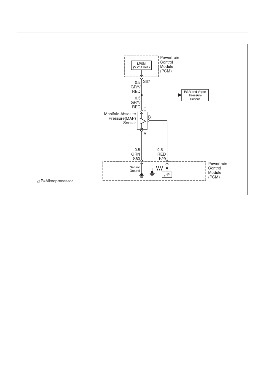
Diagnostic Trouble Code (DTC) P0108 MAP Sensor Circuit High Voltage

060R200051

Circuit Description

The manifold absolute pressure (MAP) sensor responds
to changes in intake manifold pressure (vacuum).  The
MAP sensor signal voltage to the powertrain control
module (PCM) varies from below 2 volts at idle (high
vacuum) to above 4 volts with the key “ON”, engine not
running or at wide-open throttle (low vacuum).
The MAP sensor is used to determine manifold pressure
changes while the linear EGR flow test diagnostic is being
run (refer to 

DTC P0401), to determine engine vacuum

level for some other diagnostics and to determine
barometric pressure (BARO).  The PCM monitors the
MAP signals for voltages outside the normal range of the
MAP sensor.  If the PCM detects a MAP signal voltage
that is excessively high, DTC P0108 will be set.

Conditions for Setting the DTC

D

No TP sensor DTCs present.

D

Engine is running for more than 10 seconds.

D

Throttle position is below 3% if engine speed is below
1000 RPM.

D

Throttle position is below 10% if engine speed is above
1000 RPM.

D

The MAP sensor indicates an intermittent manifold
absolute pressure above 80 kPa for a total of
approximately 10 seconds over a 16-second period.

Action Taken When the DTC Sets

D

The PCM will ON the MIL after second trip with
detected fault.

D

The PCM will default to a BARO value of 79.3 kPa.

D

The PCM will store conditions which were present
when the DTC was set as Freeze Frame and in the
Failure Records data.

Conditions for Clearing the MIL/DTC

D

The PCM will turn the MIL “OFF” on the third
consecutive trip cycle during which the diagnostic has
been run and the fault condition is no longer present.

D

A history DTC P0108 will clear after 40 consecutive
warm-up cycles have occurred without a fault.

D

DTC P0108 can be cleared by using the Tech 2 “Clear
Info” function or by disconnecting the PCM battery
feed.

Diagnostic Aids

Check for the following conditions:

D

The MAP sensor shares a 5 Volt reference with the
Fuel Tank Pressure Sensor (Vapor Pressure Sensor).
If these codes are also set, it could indicate a problem
with the 5 Volt reference circuit.

D

The MAP sensor shares a ground with the Fuel Tank
Pressure Sensor, the ECT sensor, and the
Transmission Fluid Temperature sensor.

D

Poor connection at PCM – Inspect harness connectors
for backed-out terminals, improper mating, broken

6E–147

6VE1 3.5L ENGINE DRIVEABILITY AND EMISSIONS

locks, improperly formed or damaged terminals, and
poor terminal-to-wire connection.

D

Damaged harness – Inspect the wiring harness for
damage.  If the harness appears to be OK, observe the
MAP display on the Tech 2 while moving connectors
and wiring harnesses related to the sensor.  A change
in the display will indicate the location of the fault.

If DTC P0108 cannot be duplicated, the information
included in the Failure Records data can be useful in
determining vehicle mileage since the DTC was last set. If
it is determined that the DTC occurs intermittently,
performing the DTC P1108 Diagnostic Chart may isolate
the cause of the fault.

DTC P0108 – MAP Sensor Circuit High Voltage


Step

Action

Value(s)

Yes

No

1

Was the “On-Board Diagnostic (OBD) System Check”
performed?

Go to 

Step 2

Go to 

OBD

System

Check

2

1. If the engine idle is rough, unstable or incorrect,

repair the idle problem before using this chart. Refer
to 

Symptoms section.

2. With the engine idling, note the MAP value on the

Tech 2.

Is the MAP reading above the specified value?

90 kPa

Go to 

Step 4

Go to 

Step 3

3

1. Ignition “ON”, engine “OFF”.
2. Review and record Tech 2 Failure Records data.
3. Operate the vehicle within Failure Records

conditions as noted.

4. Using a Tech 2, monitor “DTC” info for DTC P0108.

Does the Tech 2 indicate DTC P0108 failed this
ignition?

Go to 

Step 4

Refer to

Diagnostic

Aids

4

1. Ignition “OFF”.
2. Disconnect the MAP sensor electrical connector.
3. Ignition “ON”.
4. Note the MAP sensor voltage displayed on the Tech

2. (If no, start with diagnostic chart for other sensors
in the circuit and see if 5V returns.)

Is the MAP sensor voltage at the specified value?

11 kPa   0.0

V

Go to 

Step 5

Go to 

Step 6

5

Probe the sensor ground circuit with a test light to B+.

Is the test light “ON”?

Go to 

Step 7

Go to 

Step 9

6

1. Check the MAP signal circuit for a short to voltage or

a short to the 5 volt reference circuit.

2. If the MAP sensor signal circuit is shorted, repair

circuit as necessary.

Was the MAP sensor signal circuit shorted?

Verify repair

Go to 

Step 11

7

1. Check for a poor sensor ground terminal connection

at the MAP sensor electrical connector.

2. If a problem is found, replace the faulty terminal.

Did the terminal require replacement?

Verify repair

Go to 

Step 8

8

Check for a plugged or leaking vacuum supply to the
MAP sensor.

Is the vacuum supply plugged or leaking?

Verify repair

Go to 

Step 12

9

1. Check for a poor sensor ground terminal connection

at the PCM.

2. If a problem is found, replace the faulty terminal.

Did the terminal require replacement?

Verify repair

Go to 

Step 10

6E–148

6VE1 3.5L ENGINE DRIVEABILITY AND EMISSIONS

DTC P0108 – MAP Sensor Circuit High Voltage

  (Cont'd)

Step

No

Yes

Value(s)

Action

10

1. Check the continuity of the MAP sensor ground

circuit.

2. If the MAP sensor ground circuit measures over 5

ohms, repair open or poor connection.

Was a condition found and corrected?

Verify repair

Go to 

Step 11

11

Replace the PCM.

IMPORTANT: The replacement PCM must be
programmed.  Refer to 

On-Vehicle Service in

Powertrain Control Module and Sensors for
procedures.

And also refer to latest Service Bulletin.

Check to see if the Latest software is released or not.
And then Down Load the LATEST PROGRAMMED
SOFTWARE to the replacement PCM.

Is the action complete?

Verify Repair

12

Replace the MAP sensor.

Is the action complete?

Verify repair

6E–149

6VE1 3.5L ENGINE DRIVEABILITY AND EMISSIONS

Diagnostic Trouble Code (DTC) P0112 IAT Sensor Circuit Low Voltage

D06RY00147

Circuit Description

The intake air temperature (IAT) sensor is a thermistor
which measures the temperature of the air entering the
engine.  The powertrain control module (PCM) applies 5
volts through a pull-up resistor to the IAT sensor.  When
the intake air is cold, the sensor resistance is high and the
PCM will monitor a high signal voltage on the IAT signal
circuit.  If the intake air is warm, the sensor resistance is
lower, causing the PCM to monitor a lower voltage.  DTC
P0112 will set when the PCM detects an excessively low
signal voltage on the intake air temperature sensor signal
circuit.

Conditions for Setting the DTC

D

The engine has been running for over 15 seconds.

D

Vehicle speed is greater than 30 mph (48 km/h) .

D

IAT signal voltage indicates and intake air temperature
greater than 148

°

C (298

°

F) (about 5 volts) for a total

of 12.5 seconds over a 25-second period of time.

Action Taken When the DTC Sets

D

The PCM will ON the MIL after second trip with
detected fault.

D

The PCM will store conditions which were present
when the DTC was set as Freeze Frame and in the
Failure Records data.

Conditions for Clearing the MIL/DTC

D

The PCM will turn the MIL “OFF” on the third
consecutive trip cycle during which the diagnostic has
been run and the fault condition is no longer present.

D

A history DTC P0112 will clear after 40 consecutive
warm-up cycles have occurred without a fault.

D

DTC P0112 can be cleared by using the Tech 2 “Clear
Info” function or by disconnecting the PCM battery
feed.

Diagnostic Aids

Check for the following conditions:

D

Poor connection at PCM – Inspect harness connectors
for backed-bout terminals, improper mating, broken
locks, improperly formed or damaged terminals, and
poor terminal-to-wire connection.

D

Damaged harness – Inspect the wiring harness for
damage.  If the harness appears to be OK, observe the
IAT display on the Tech 2 while moving connectors and
wiring harnesses related to the IAT sensor. A change
in the IAT display will indicate the location of the fault.

If DTC P0112 cannot be duplicated, the information
included in the Failure Records data can be useful in
determining vehicle mileage since the DTC was last set.


Content   ..  277  278  279  280   ..