Isuzu Amigo / Axiom / Trooper / Rodeo / VehiCross. Manual - part 215


  Index      Isuzu     Isuzu Amigo / Axiom / Trooper / Rodeo / VehiCross - service repair manual 1999-2002 year


Search            


Content   ..  213  214  215  216   ..


Isuzu Amigo / Axiom / Trooper / Rodeo / VehiCross. Manual - part 215


6A–47

ENGINE MECHANICAL (6VE1 3.5L)

Installation

CAUTION: When  assembling the engine and
transmission, confirm that dowels have been
mounted in the specified positions at the engine
side.

NOTE: Take care that dowel positions are different
between the manual transmission and the automatic
transmission.
If the engine is assembled in the condition that the dowels
have not been mounted in the specified positions, the
transmission may be damaged.

012RS009

1. Install engine assembly. Tighten engine mount fixing

bolts to frame to the specified torque.

Torque: 41 N·m (30 lb ft)

2. Reconnect fuel hose to fuel pipe on engine.
3. Install transmission assembly. Refer to Transmission

section in this manual.

4. Reconnect two heater hoses to engine.
5. Install flywheel dust covers.
6. Install exhaust pipe and temporally tighten two (each

bank) rear exhaust flange nuts then tighten three stud
nuts (each bank) between exhaust manifold and
exhaust pipe, finally tighten rear side nuts to the
specified torque.

Torque:
Nuts: 43 N·m (32 lb ft)
Stud nuts: 67 N·m (49 lb ft)
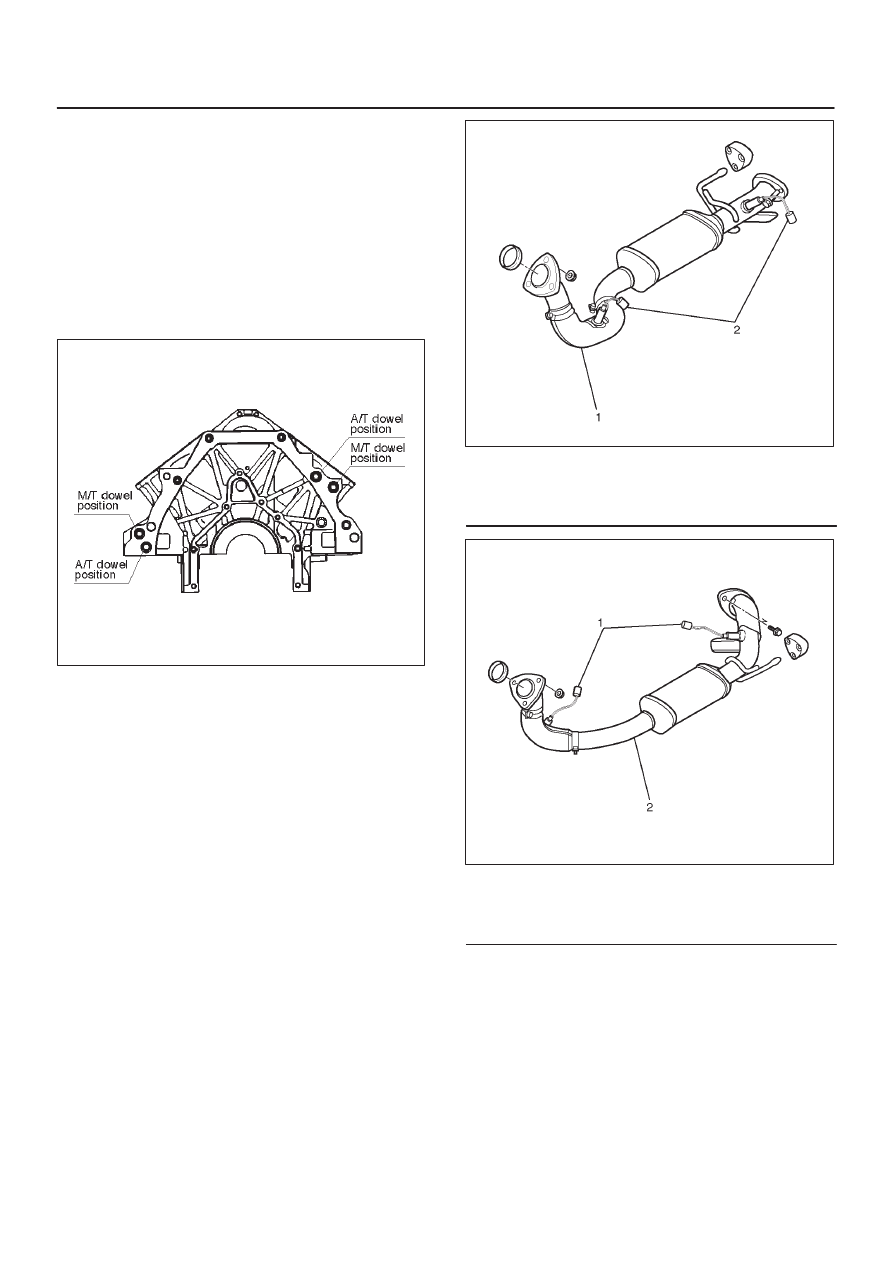
150R200002

Legend

(1) Exhaust Front Pipe RH
(2) O

2

 Sensor

150R200003

Legend

(1) O

2

 Sensor

(2) Exhaust Front Pipe LH

7. Reconnect O

2

 sensor connector.

8. Install cooling fan assembly and tighten bolts/nuts to

the specified torque.

Torque : 22 N·m (16 lb ft) for fan pulley and fan
bracket.

Torque : 7.5 N·m (66.4 lb in) for fan and clutch
assembly.

6A–48

ENGINE MECHANICAL (6VE1 3.5L)

9. Install air conditioner compressor to engine and

tighten to the specified torque.

Torque :
M8 bolts : 22 N·m (16 lb ft)
M10 bolts : 43 N·m (32 lb ft)

10. Install power steering pump, tighten fixing bolt to the

specified torque.

Torque :
M8 bolts : 22N·m (16 lb ft)
M10 bolts : 46 N·m (34 lb ft)

11. Move drive belt tensioner to loose side using wrench,

then install drive belt to normal position.

850RW001

Legend

(1) Crankshaft Pulley
(2) Cooling Fan Pulley
(3) Tensioner
(4) Generator
(5) Air Conditioner Compressor
(6) Power Steering Oil Pump
(7) Idle Pulley
(8) Drive Belt

12. Install upper fan shroud.
13. Reconnect radiator upper and lower hoses.
14. Reconnect coolant reserve tank hose to radiator.
15. Reconnect generator harness connector.
16. Reconnect starter harness connector.
17. Reconnect bonding cable terminal on left bank
18. Reconnect bonding cable terminal on the back of right

dash panel.

19. Reconnect ground cable between engine and

chassis.

20. Reconnect harness connector to transmission and

install transmission harness bracket on engine left
side.

21. Reconnect three engine harness connectors.
22. Reconnect vacuum booster hose.
23. Reconnect canister vacuum hose.

24. Install air cleaner assembly.
25. Reconnect air duct.
26. Reconnect throttle position sensor harness

connector.

025RY001

Legend

(1) Throttle Position Sensor Connector
(2) Throttle Valve Assembly

27. Reconnect manifold absolute pressure sensor

harness connectors.

28. Reconnect ion sensing module connectors as shown

in the illustration.

060RY00111

Legend

(1) Green Connector
(2) Blue Connector
(3) Identification Mark (6VE1 Engine Only)

29. Install engine hood to the original position.

D

Refer to installation procedure for Body section in
this manual.

6A–49

ENGINE MECHANICAL (6VE1 3.5L)

Cylinder Head

Cylinder Head and Associated Parts

011RW008

Legend

(1) Spark Plug
(2) Cylinder Head Bolt
(3) Camshaft Drive Gear Pulley Fixing Bolt
(4) Camshaft Drive Gear Pulley
(5) Camshaft Bearing Cap Fixing Bolt
(6) Camshaft Bearing Cap
(7) Camshaft Exhaust

(8) Camshaft Intake
(9) Retainer Fixing Bolt

(10) Retainer Assembly

(11) Tappet with Shim

(12) Split Collar
(13) Valve Spring and Spring Upper Seat
(14) Valve

6A–50

ENGINE MECHANICAL (6VE1 3.5L)

Disassembly

NOTE:

D

During disassembly, be sure that the valve train
components are kept together and identified so that
they can be reinstalled in their original locations.

D

Before removing the cylinder head from the engine
and before disassembling the valve mechanism,
perform a compression test and note the results.

1. Remove camshaft drive gear pulley fixing bolt (3),

then pulley (4).

2. Remove camshaft bearing cap fixing bolt (5),

camshaft bearing cap (6), then camshaft exhaust (7),
and intake side (8).

3. Remove tappet with shim (11).
4. Use the J–8062 valve spring compressor and

J–42898 valve spring compressor adapter to remove
the split collar (12), valve spring with upper seat (13)
and valve (14).

014RW042

5. Remove spark plug (1).

CAUTION: Do not remove the spark plugs when the
head and plugs are hot. Clean dirt and debris from
spark plug recess areas before removal.

Clean

Cylinder head

Carefully remove all varnish, soot and carbon from the
bare metal. Do not use surface conditioning disc on any
gasket sealing surface.

Inspection and Repair

1. Inspect cylinder head gasket and mating surfaces for

leaks, corrosion and blow–by. If the gasket has failed,
determine the cause.
– Insufficient torque on head bolts
– Improper installation
– Loose or warped cylinder head
– Missing dowel pins
– Warped case surface

2. Inspect cylinder head for cracks, especially between

valve seats and in the exhaust ports.

3. Inspect cylinder head deck for corrosion, sand

particles in head and porosity.

CAUTION:

D

Do not attempt to weld the cylinder head. Replace
it.

D

Do not reuse cylinder head bolts.

4. Inspect cylinder head deck, common chamber and

exhaust manifold mating surfaces for flatness. These
surfaces may be reconditioned by milling. If the
surfaces are “out of flat” with “round” by more than
specification, the surface should be ground to within
specifications. Replace the head if it requires
machining beyond the repairable limit.

Head surface and manifold surface
Standard: 0.05 mm (0.002 in) or less
Warpage limit: 0.2 mm (0.0079 in)
Maximum Repairable limit: 0.2 mm (0.0079 in)

Head height
Standard height : 133.2 mm (5.2441 in)
Warpage limit : 0.2 mm (0.0079 in)
Maximum Repairable limit : 133.0 mm (5.2362 in)

011RW019

5. Water jacket sealing plugs seating surfaces.


Content   ..  213  214  215  216   ..