Isuzu Amigo / Axiom / Trooper / Rodeo / VehiCross. Manual - part 213
6A–39
ENGINE MECHANICAL (6VE1 3.5L)
3. Remove oil strainer fixing bolts, remove oil strainer
assembly with O-ring.
050RW002
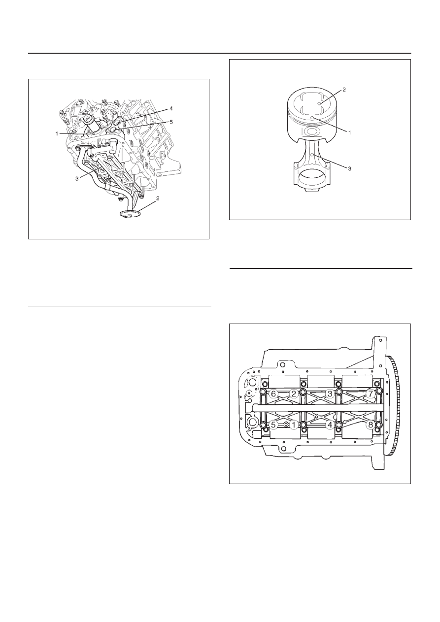
Legend
(1) Oil Pump
(2) Oil Strainer
(3) Oil Gallery
(4) From Oil Filter
(5) To Oil Filter
4. Remove three fixing bolts, oil pipe with O-ring.
5. Remove eight fixing bolts, oil gallery.
6. Remove piston with connecting rod assembly.
(before removing the bearing cap, remove carbon on
the top of cylinder bore and push piston with
connecting rod out from the top of cylinder bore.)
Installation
1. Install piston with connecting rod assembly.
D
Apply engine oil to cylinder bore, connecting rod
bearing and crank pin.
When installing the piston, its front mark must face
the engine front side.
D
The bearing cap number must be the same as
connecting rod number.
D
Apply engine oil to the thread and seating surface of
each nut.
D
Tighten nuts to the specified torque.
Torque : 54 N·m (40 lb ft)
D
After tightening the nuts, make sure that the
crankshaft rotates smoothly.
NOTE: Do not apply engine oil to the bearing back faces
and connecting rod bearing fitting surfaces.
015RW003
Legend
(1) Piston Front Mark
(2) Piston Grade
(3) Connecting Rod Front Mark
2. Install oil gallery and tighten the bolts in two steps, in
the order shown in illustration.
Torque :
1st step : 29 N·m (22 lb ft)
2nd step : 55
°
–65
°
051RS009
3. Install oil pipe with O-ring.
Torque : 10 N·m (87 lb in)
4. Install oil strainer assembly with O-ring.
Torque : 25 N·m (18 lb ft)
5. Install crankcase with oil pan.
D
Refer to installation procedure for Oil Pan and
Crankcase in this manual.
6. Install cylinder head assembly.
D
Refer to installation procedure for Cylinder Head in
this manual.