Isuzu Amigo / Axiom / Trooper / Rodeo / VehiCross. Manual - part 210
6A–27
ENGINE MECHANICAL (6VE1 3.5L)
Timing Belt
Removal
1. Disconnect battery ground cable.
2. Remove air cleaner assembly.
3. Remove radiator upper fan shroud from radiator.
4. Move drive belt tensioner to loose side using wrench
then remove drive belt.
850RW001
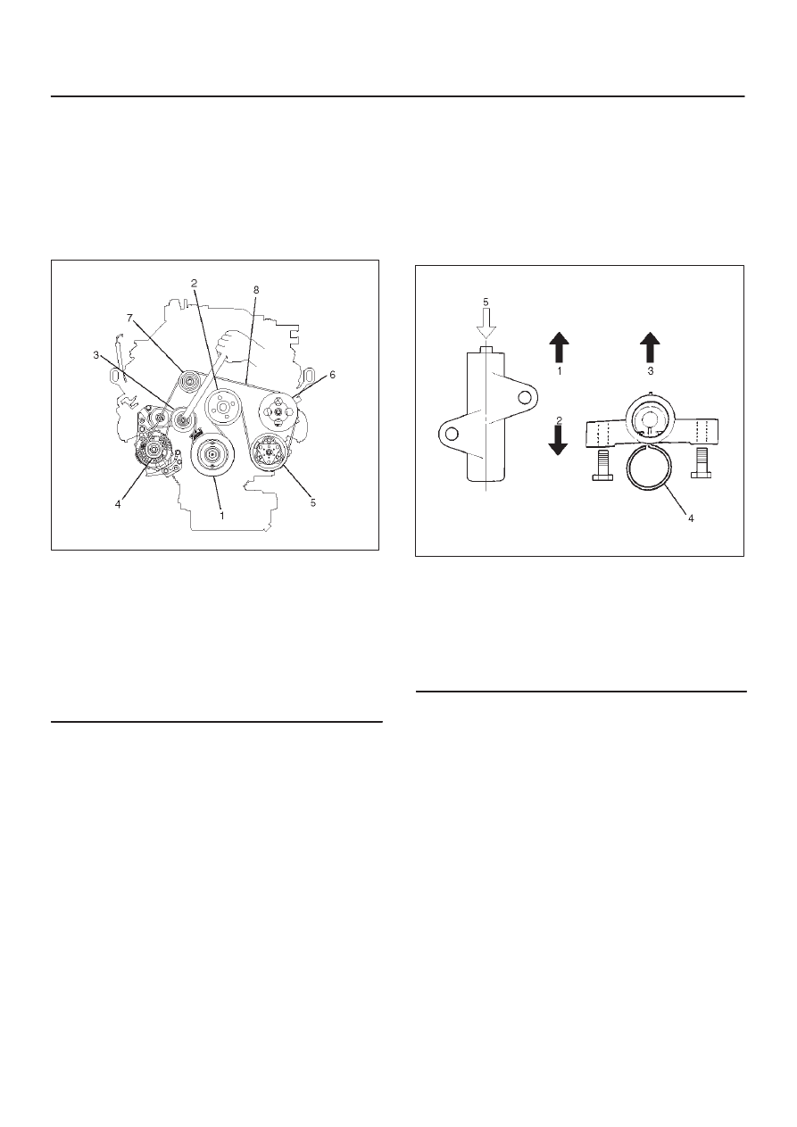
Legend
(1) Crankshaft Pulley
(2) Cooling Fan Pulley
(3) Tensioner
(4) Generator
(5) Air Conditioner Compressor
(6) Power Steering Oil Pump
(7) Idle Pulley
(8) Drive Belt
5. Remove cooling fan assembly four nuts, then the
cooling fan assembly.
6. Remove cooling fan drive pulley assembly.
7. Remove idle pulley assembly.
8. Remove serpentine belt tensioner assembly.
9. Remove power steering pump assembly.
10. Remove crankshaft pulley assembly using J-8614-01
crankshaft holder, hold crankshaft pulley remove
center bolt, then the pulley.
11. Remove right side timing belt cover then left side
timing belt cover.
12. Remove lower timing belt cover
13. Remove pusher.
CAUTION: The pusher prevents air from entering
the oil chamber. Its rod must always be facing
upward.
014R100020
Legend
(1) Up Side
(2) Down Side
(3) Direction For Installation
(4) Locking Pin
(5) Apply a force of 980 N (220 lb) when
compressing the pusher rod.
14. Remove timing belt.
CAUTION:
1. Do not bend or twist the belt, otherwise its core
could be damaged. The belt should not be bent at
a radius less than 30 mm (1.1811 in).
2. Do not allow oil or other chemical substances to
come in contact with the belt. They will shorten
the life.
3. Do not attempt to pry or stretch the belt with a
screw driver or any other tool during installation.
4. Store timing belt in a cool and dark place. Never
expose the belt direct sunlight or heat.