Isuzu Amigo / Axiom / Trooper / Rodeo / VehiCross. Manual - part 208


  Index      Isuzu     Isuzu Amigo / Axiom / Trooper / Rodeo / VehiCross - service repair manual 1999-2002 year


Search            


Content   ..  206  207  208  209   ..


Isuzu Amigo / Axiom / Trooper / Rodeo / VehiCross. Manual - part 208


6A–19

ENGINE MECHANICAL (6VE1 3.5L)

Cylinder Head Cover LH

Removal

1. Disconnect battery ground cable.
2. Remove engine cover from the dowels on the

common chamber.

F06RY001

3. Disconnect positive crankcase ventilation hose.
4. Remove ground cable fixing bolt on cylinder head

cover.

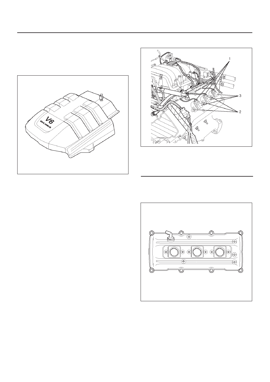
5. Ignition coil connector and ignition coil.

D

Disconnect the three connectors from the ignition
coils.

D

Remove harness bracket bolt on cylinder head
cover.

D

Remove fixing bolts on ignition coils.

060RY022

Legend

(1) Ignition Coil Connector
(2) Bolt
(3) Ignition Coil Assemblies

6. Disconnect fuel injector harness connector then

remove fuel injector harness bracket bolt.

7. Remove eight fixing bolts, then the cylinder head

cover.

010RW001

NOTE: Where do you refer the tech in case of bolt
removal difficulties.

6A–20

ENGINE MECHANICAL (6VE1 3.5L)

Installation

1. Install cylinder head cover.

D

Clean the sealing surface of cylinder head and
cylinder head cover to remove oil and sealing
materials completely.

D

Apply sealant (TB-1207B or equivalent) of bead
diameter 2-3 mm at eight place of arched area of
camshaft bearing cap on front and rear sides.

D

The cylinder head cover must be installed with in 5
minutes after sealant application to prevent
hardening of sealant.

D

Tighten bolts to the specified torque.

Torque : 9 N·m (78 lb in)

010RW008

2. Install fuel injection harness bracket and tighten bolt

to the specified torque.

Torque : 9 N·m (78 lb in)

3. Connect ignition coil connector and ignition coil, then

tighten bolt to the specified torque.

Torque : 4 N·m (35 lb in)

060RY022

Legend

(1) Ignition Coil Connector
(2) Bolt
(3) Ignition Coil Assembly

CAUTION: Ignition coil assembly #6 is different
from ignition coil assembly from #1 to #5. Ignition
coil assembly #6 is short type. So, note it when
installing ignition coil assembly of #6.

060RY00002

Legend

(1) Long Type Ignition Coil Assemblies (# 1 

 # 5)

(2) Short Type Ignition Coil Assembly (# 6)

4. Connect ground cable and tighten bolts to the

specified torque.

Torque : 9 N·m (78 lb in)

5. Install positive crankcase ventilation hose.
6. Install engine cover mating with the dowels.

6A–21

ENGINE MECHANICAL (6VE1 3.5L)

Cylinder Head Cover RH

Removal

1. Disconnect battery ground cable.
2. Remove engine cover from the dowele on the

common chamber.

F06RY001

3. Disconnect ventilation hose from cylinder head cover.
4. Disconnect three ignition coil connectors from ignition

coils and remove harness bracket bolts on cylinder
head cover then remove ignition coil fixing bolts on
ignition coils and remove ignition coils.

5. Disconnect fuel injector harness connector then

remove fuel injector harness bracket bolt.

6. Remove eight fixing bolts then the cylinder head

cover.

010RW002

Installation

1. Install cylinder head cover.

D

Clean the sealing surface of cylinder head and
cylinder head cover to remove oil and sealing
materials completely. 
Apply sealant (TB-1207B or equivalent) bead
(diameter 2-3 mm) at eight places of arched areas
of camshaft bracket on front and rear sides.

D

The cylinder head cover must be installed within 5
minutes after sealant application to prevent
premature hardening of sealant.

D

Tighten bolts to the specified torque.

Torque : 9 N·m (78 lb in)

014RW019

2. Tighten fuel injector harness bracket bolts to

specified torque then reconnect fuel injector harness
connector.

Torque : 7.8 N·m (69 lb in)

3. Connect ignition coil connector and tighten ignition

coil fixing bolts to specified torque.

Torque : 4 N·m (35 lb in)

4. Connect ventilation hose to cylinder head.
5. Install engine cover mating with the dowels.

6A–22

ENGINE MECHANICAL (6VE1 3.5L)

Common Chamber

Removal

1. Disconnect battery ground cable.
2. Remove air cleaner duct assembly.

013RY00001

Legend

(1) Positive Crankcase Ventilation Hose Connector
(2) Intake Air Temperature Sensor
(3) Air Cleaner Duct Assembly
(4) Air Flow Sensor

3. Disconnect vacuum booster hose from common

chamber.

4. Disconnect connector from manifold absolute

pressure sensor, Ion sensing module, throttle
position sensor, solenoid valve, electric vacuum
sensing valve, and EGR valve.

5. Disconnect vacuum hose on canister VSV and

positive crankcase ventilation hose, fuel rail
assembly with pressure control valve bracket.

6. Remove ventilation hose from throttle valve and

intake duct and remove water hose.

7. Remove the four throttle body fixing bolts.
8. Remove exhaust gas recirculation valve assembly

fixing bolt and nut on common chamber and remove
EGR valve assembly.

9.  Remove two bolts from common chamber rear side

to remove fuel hose bracket.

10. Remove common chamber four bolts and four nuts

then remove the common chamber.

025RY002

Legend

(1) Common Chamber
(2) Throttle Valve Assembly
(3) Bolt

Installation

1. Install common chamber and tighten bolts and nuts to

the specified torque.

Torque :
Bolt : 25 N·m (18 lb ft)
Nut : 25 N·m (18 lb ft)

2. Install fuel hose bracket and tighten bolts to specified

torque.

Torque : 10 N·m (87 lb in)

3. Install exhaust gas recirculation valve assembly and

tighten bolt and nut to the specified torque.

Torque : 25 N·m (18 lb ft)

4. Install throttle body and tighten bolts to the specified

torque.

Torque : 25 N·m (18 lb ft)

5. Install ventilating hose to throttle valve and intake

duct.

6. Connect vacuum hoses on canister VSV and positive

crankcase ventilation hose. Tighten bolts for fuel rail
assembly with pressure control valve bracket.

Torque : 25 N·m (18 lb ft)


Content   ..  206  207  208  209   ..