Isuzu Amigo / Axiom / Trooper / Rodeo / VehiCross. Manual - part 209


  Index      Isuzu     Isuzu Amigo / Axiom / Trooper / Rodeo / VehiCross - service repair manual 1999-2002 year


Search            


Content   ..  207  208  209  210   ..


Isuzu Amigo / Axiom / Trooper / Rodeo / VehiCross. Manual - part 209


6A–23

ENGINE MECHANICAL (6VE1 3.5L)

7. Connect each connector.
8. Connect vacuum booster hose.
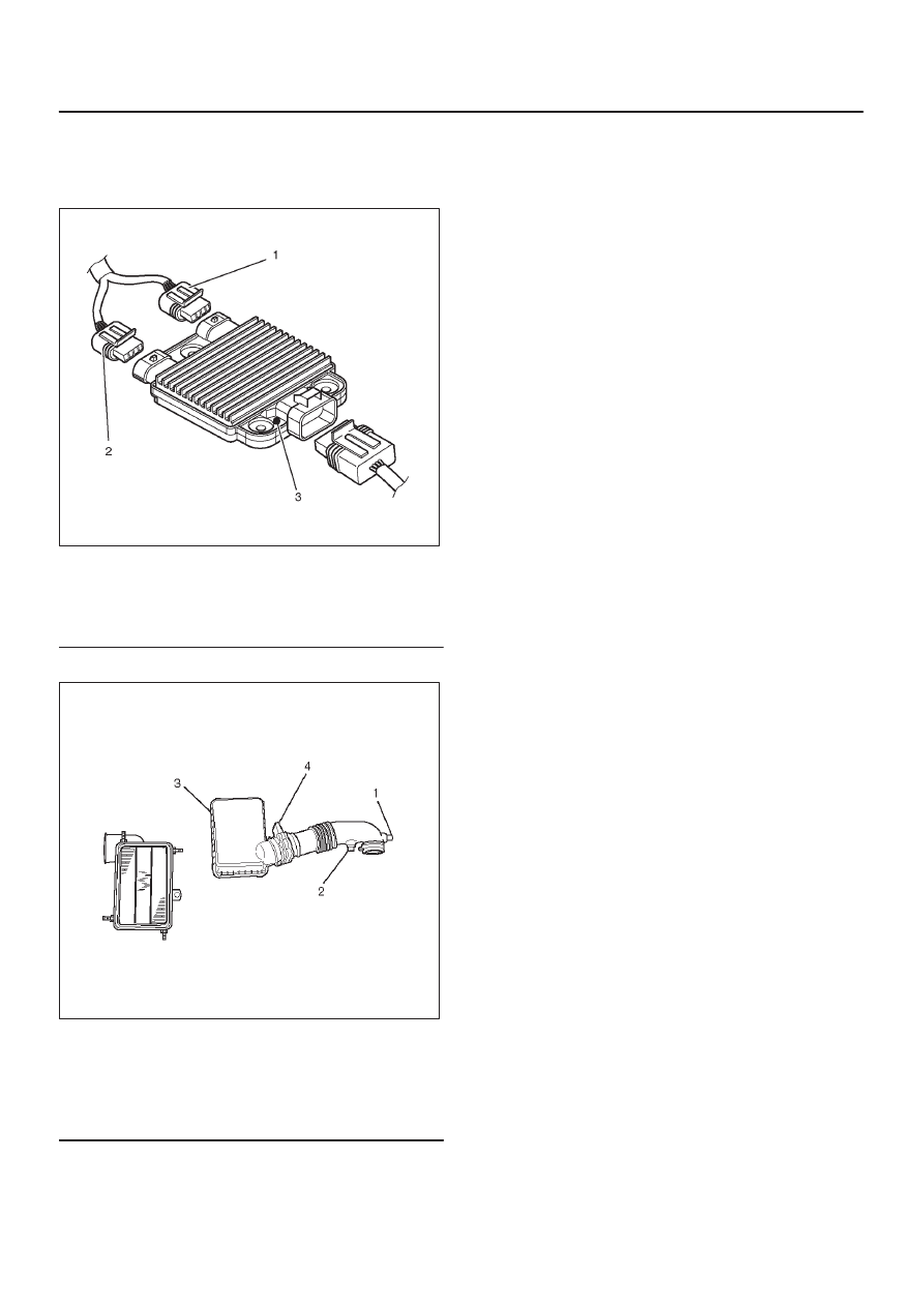
9. Connect the Ion sensing module connectors as

shown in the illustration.

060RY00111

Legend

(1) Green Connector
(2) Blue Connector
(3) Identification Mark (6VE1 Engine Only)

10.  Install air cleaner duct assembly.

013RY00001

Legend

(1) Positive Crankcase Ventilation Hose Connector
(2) Intake Air Temperature Sensor
(3) Air Cleaner Duct Assembly
(4) Mass Air Flow Sensor

6A–24

ENGINE MECHANICAL (6VE1 3.5L)

Exhaust Manifold LH

Removal

1. Disconnect battery ground cable.
2. Disconnect O

2

 sensor connector.

3. Remove exhaust front pipe three stud nuts from

exhaust side and two bolts from rear end of exhaust
front pipe.

150R100011

Legend

(1) Exhaust Front Pipe LH
(2) O

2

 Sensor

4. Remove exhaust manifold eight fixing nuts and

remove exhaust manifold from the engine.

Installation

1. Install exhaust manifold and tighten exhaust manifold

fixing nuts to the specified torque with new nuts.

Torque: 57 N·m (42 lb ft)

2. Install exhaust front pipe and tighten three stud nuts

and two bolts to the specified torque.

Torque : 
Stud nuts: 67 N·m (49 lb ft)
Bolts: 43 N·m (32 lb ft)

150R100011

Legend

(1) O

2

 Sensor

(2) Exhaust Front Pipe LH

3. Reconnect O

2

 sensor connector.

6A–25

ENGINE MECHANICAL (6VE1 3.5L)

Exhaust Manifold RH

Removal

1. Disconnect battery ground cable.
2. Remove torsion bar. Refer to removal procedure in

Front Suspension section.

3. Remove exhaust front pipe three stud nuts and two

bolts then disconnect exhaust front pipe.

150R100013

Legend

(1) Exhaust Front Pipe RH
(2) O

2

 Sensor

4. Remove exhaust manifold eight fixing nuts then the

exhaust manifold.

Installation

1. Install exhaust manifold and tighten nuts to the

specified torque.

Torque : 57 N·m (42 lb ft)

2. Install exhaust front pipe and tighten three stud nuts

and two bolts to the specified torque.

Torque:
Stud nuts: 67 N·m (49 lb ft)
Bolts: 43 N·m (32 lb ft)

3. Install the torsion bar and readjust the vehicle height.

Refer to installation and vehicle height adjustment
procedure for front suspension.

6A–26

ENGINE MECHANICAL (6VE1 3.5L)

Crankshaft Pulley

Removal

1. Disconnect battery ground cable.
2. Remove air cleaner assembly.

013RY00001

Legend

(1) Positive Crankcase Ventilation Hose Connector
(2) Intake Air Temperature Sensor
(3) Air Cleaner Duct Assembly
(4) Air Flow Sensor

3. Remove radiator upper fan shroud from radiator.
4. Move serpentine belt tensioner to loose side using

wrench then remove serpentine belt.

850RW001

Legend

(1) Crankshaft Pulley
(2) Cooling Fan Pulley
(3) Tensioner
(4) Generator
(5) Air Conditioner Compressor
(6) Power Steering Oil Pump
(7) Idle Pulley
(8) Driver Belt

5. Remove cooling fan assembly four fixing nuts, then

the cooling fan assembly.

6. Remove crankshaft pulley assembly using J-8614-01

crankshaft holder, hold crankshaft pulley then
remove center bolt and pulley.

Installation

1. Install crankshaft pulley using J-8614-01 crankshaft

holder, hold the crankshaft pulley and tighten center
bolt to the specified torque.

Torque : 167 N·m (123 lb ft)

2. Install cooling fan assembly and tighten bolts/nuts to

the specified torque.

Torque : 22 N·m (16 lb ft) for fan pulley and fan
bracket.

Torque : 7.5 N·m (66.4 lb in) for fan and clutch
assembly.

3. Move serpentine belt tensioner to loose side using

wrench, then install serpentine belt to normal
position.

4. Install radiator upper fan shroud.
5. Install air cleaner assembly.


Content   ..  207  208  209  210   ..