Isuzu Amigo / Axiom / Trooper / Rodeo / VehiCross. Manual - part 194
5C–93
POWER–ASSISTED BRAKE SYSTEM
Front Disc Brake Rotor
Inspection
In the manufacturing of the brake rotor, all the tolerances
regarding surface finish, parallelism and lateral runout are
held very closely. Maintaining these tolerances provides
the surface necessary to assure smooth brake operation.
Lateral Runout
Lateral runout is the movement of the rotor from side to
side as it rotates on the spindle. This could also be
referred to as “rotor wobble”.
This movement causes the piston to be knocked back into
its bore. This results in additional pedal travel and a
vibration during braking.
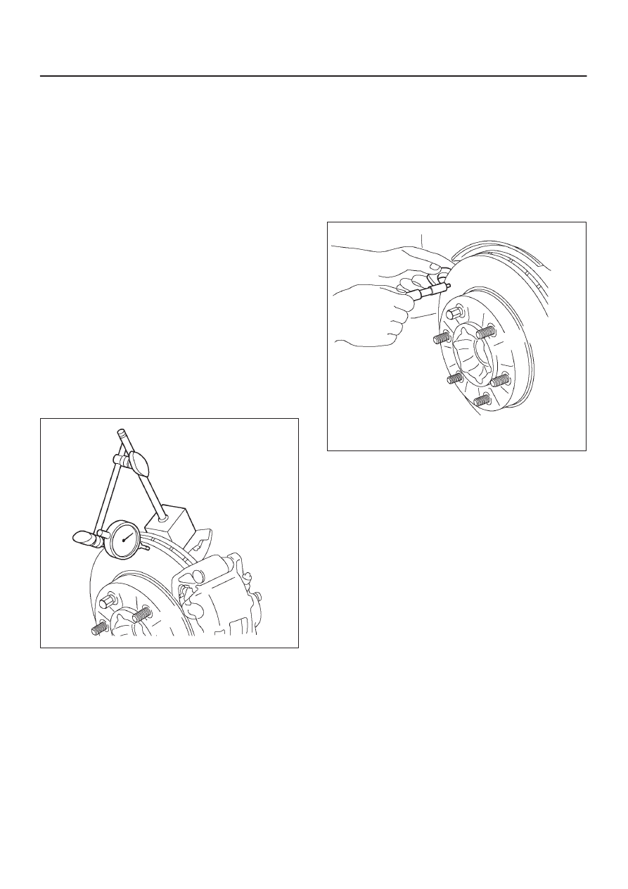
Checking Lateral Runout
1. Adjust the wheel bearing correctly, refer to
Differential
in Section 4A.
2. Attach the dial indicator accordingly so that the stem
contacts the rotor surface to approximately 29mm
(1.14 in) from the rotor edge.
3. Rotate the rotor one complete turn and inspect for
signs of lateral runout. Lateral runout should not
exceed 0.13 mm (0.005 in).
Maximum runout: 0.13 mm (0.005 in)
411R200008
Parallelism
Parallelism is the measurement of thickness of the rotor
at four or more points around the circumference of the
rotor. All measurement must be made at 29 mm (1.14 in)
from the edge of the rotor.
The rotor thickness must not vary more than 0.010 mm
(0.0004 in) from point to point.
Maximum runout: 0.010 mm (0.0004 in)
411R200007
Replacing Brake Rotors
When installing new brake rotors, do not refinish the
surfaces. These parts are at the correct level of surface
finish.
Refinishing Brake Rotors
Accurate control of the rotor tolerances is necessary for
proper performance of the disc brakes. Machining of the
rotor should be done only with precision equipment. All
brake rotors have a minimum thickness dimension cast
into them. This dimension is the minimum wear
dimension and not a refinish dimension. The minimum
wear dimension is 24.60 mm (0.969 in). The minimum
refinish dimension is 26.00 mm (1.024 in).
When refinishing rotors, always use sharp cutting tools or
bits. Dull or worn tools leave a poor surface finish which
will affect initial braking performance. Vibration
dampening attachments should always be used when
refinishing braking surfaces. These attachments
eliminate tool chatter and will result in better surface
finish.
After refinishing, replace any rotor that does not meet the
minimum thickness of 26.00 mm (1.024 in). Do not use a
brake rotor that exceeds the manufacturers
specifications.