Isuzu Amigo / Axiom / Trooper / Rodeo / VehiCross. Manual - part 192


  Index      Isuzu     Isuzu Amigo / Axiom / Trooper / Rodeo / VehiCross - service repair manual 1999-2002 year


Search            


Content   ..  190  191  192  193   ..


Isuzu Amigo / Axiom / Trooper / Rodeo / VehiCross. Manual - part 192


5C–85

POWER–ASSISTED BRAKE SYSTEM

Vacuum Booster Assembly

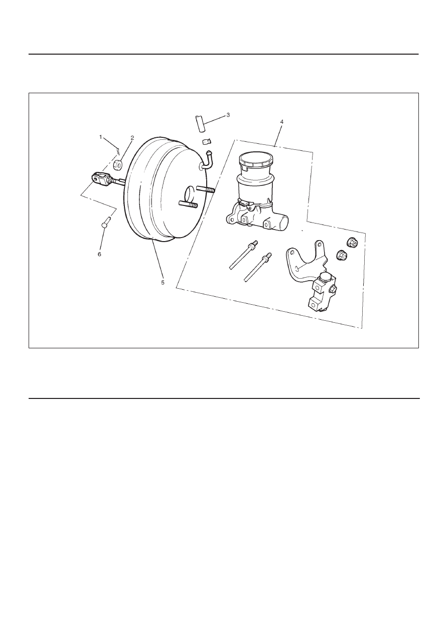
Vacuum Booster Assembly and Associated Parts

331R200004

Legend

(1) Snap Pin
(2) Vacuum Booster Fixing Nut
(3) Vacuum Hose

(4) Master Cylinder
(5) Vacuum Booster
(6) Pin

Removal

1. Before removing the vacuum booster assembly,

disconnect and remove the brake pipes.

2. Remove master cylinder, refer to 

Master Cylinder

Removal in this section.

CAUTION: When removing the master cylinder from
the vacuum booster, be sure to get rid of the internal
negative pressure of the vacuum booster (by,
disconnecting the vacuum hose) in advance.
If any negative pressure remains in the vacuum
booster, the piston may possibly come out when the
master cylinder is being removed, letting the brake
fluid run out.
Do not hold the piston while removing the master cy-
liner, the piston can be easily pulled out.
Outside surface of the piston is the surface on which
seals are to slide. Care should be taken to keep the
surface free of cuts and dents.

3. Remove vacuum hose.
4. Disconnect the yoke clevis from the brake pedal.

5. Remove vacuum booster fixing nut.
6. Remove vacuum booster.

5C–86 POWER–ASSISTED BRAKE SYSTEM

Inspection and Repair

Vacuum Hose (The built in check valve)

1. Inspect the check valve (2), which is installed inside

the vacuum hose.

2. Air should pass freely from the vacuum booster (3) to

the engine (1).

3. Air should not pass from the engine (1) to the vacuum

booster (3). If it does, the check valve is inoperative
and the vacuum hose built in the check valve must be
replaced.

HEC ENGINE

360RW001

6VD1 ENGINE

360RY00004

5C–87

POWER–ASSISTED BRAKE SYSTEM

Exterior Components

Exterior Components and Associated Parts

331R200006

Legend

(1) 2 Gaskets and Spacer
(2) Vacuum Booster

(3) Plate and Seal Assembly
(4) Retainer
(5) Master Cylinder

Removal

1. Remove master cylinder. Refer to 

Master Cylinder in

this section.

2. Remove vacuum booster. Refer to 

Vacuum Booster

in this section.

3. Remove 2 gaskets and spacer.
4. Remove retainer, plate and seal assembly.

331RS003

5C–88 POWER–ASSISTED BRAKE SYSTEM

Inspection and Repair

Visual Check

Make necessary parts replacement if cuts, nicks,
excessive wear, or other abnormal conditions are found
through inspection.

NOTE: The parts listed below must be replaced with new
ones whenever the master cylinder is removed.

1. Plate and seal assembly
2. Retainer

Installation

1. Install plate and seal assembly.
2. Install retainer.
3. Install vacuum booster, refer to 

Vacuum Booster in

this section.

4. Install master cylinder, refer to 

Master Cylinder in this

section and after installation, perform brake pedal
check and adjustment. Refer to 

Brake Pedal in this

section.

Vacuum Booster Overhaul

Vacuum Booster

The vacuum booster cannot be disassembled for repair.
Replace a defective vacuum booster with a new one.


Content   ..  190  191  192  193   ..