Isuzu Amigo / Axiom / Trooper / Rodeo / VehiCross. Manual - part 195


  Index      Isuzu     Isuzu Amigo / Axiom / Trooper / Rodeo / VehiCross - service repair manual 1999-2002 year


Search            


Content   ..  193  194  195  196   ..


Isuzu Amigo / Axiom / Trooper / Rodeo / VehiCross. Manual - part 195


5C–97

POWER–ASSISTED BRAKE SYSTEM

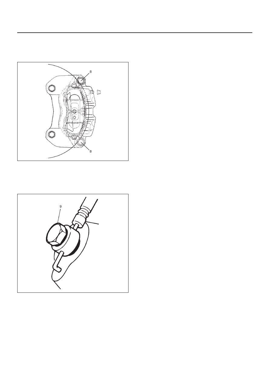
4. Install caliper assembly.
5. Install pin bolt (8) and tighten the bolt to the specified

torque.

Torque: 45 N·m (33 lb ft)

302R200010

6. Install brake flexible hose, always use new gaskets

and be sure to put the hooked edge of the flexible
hose end into the anti–rotation cavity then tighten the
I–bolt (9) to the specified torque.

Torque: 35 N·m (26 lb ft)

302R200021

7. Install wheel and tire assembly, referring to 

Wheels

and Tires System in Section 3E.

8. Bleed brakes. Refer to 

Hydraulic Brakes in this

section.

5C–98 POWER–ASSISTED BRAKE SYSTEM

Front Disc Brake Caliper

Front Disc Brake Caliper Disassembled View

302R200018

Legend

(1) Bleeder with Cap
(2) Caliper Body

(3) Piston
(4) Piston Seal
(5) Dust Boot: Piston

Disassembly

1. Insert a block of wood into the caliper and force out

the piston by blowing compressed air into the caliper
at the flexible hose attachment. This procedure must
be done prior to removal of the dust boot.
Remove piston.

WARNING: DO NOT PLACE YOUR FINGERS IN
FRONT OF THE PISTON IN AN ATTEMPT TO CATCH
OR PROTECT IT WHEN APPLYING COMPRESSED
AIR. THIS COULD RESULT IN PERSONAL INJURY.

CAUTION: Use just enough air to ease the piston
out of the bore. If the piston is blown out, it may be
damaged.

302R200012

5C–99

POWER–ASSISTED BRAKE SYSTEM

2. Remove dust boot: piston.
3. Remove piston seal.
4. Remove bleeder with cap.
5. Remove caliper body.

Inspection and Repair

Make necessary parts replacement, if wear, damage,
corrosion or any other abnormal conditions are found
through inspection.
Check the following parts:

D

Rotor

D

Cylinder body

D

Cylinder bore

D

Piston

D

Guide pin, lock pin

D

Support bracket

NOTE: The piston seal, boot ring and dust boot are to be
replaced each time the caliper is overhauled. Discard
these used rubber parts and replace them with new ones.

Reassembly

1. Install caliper body.
2. Install bleeder with cap and tighten the cap to the

specified torque.

Torque: 8 N·m (69 lb in)

3. Apply special rubber grease to the piston seal and

cylinder wall, then insert the piston seal into the
cylinder. The special rubber grease is included in the
repair kit.

302R200013

4. When inserting the piston into the cylinder, use finger

pressure only and do not use a mallet or other impact
tool, since damage to the cylinder wall or piston seal
can result.
Install piston.

302R200015

5. Apply special grease (approximately 1 g) to the piston

and attach the dust boot to the piston and caliper.
Insert the dust boot ring into the dust boot.

6. Install guide bolt and lock bolt dust boot.
7. Install the dust boot on the support bracket after

applying special grease (approximately 1 g) onto the
dust boot inner surface. Apply special grease onto the
lock pin and guide pin setting hole of the support
bracket.

302R200022

Legend

(1) Guide Pin
(2) Lock Pin
(3) Pin Boot

8. Install pin bolt and tighten the bolt to the specified

torque.

Torque: 45 N·m (33 lb ft)

5C–100POWER–ASSISTED BRAKE SYSTEM

Main Data and Specifications

General Specifications

Type

Floating, pin slide

Pad dimension

48.7 cm

@

 (7.55 in

@

)

Adjusting method

Self–adjusting

Piston diameter

45.4 mm (1.79 in) 

×

2

Disc type

Ventilated

Disc thickness

26 mm (1.02 in)

Disc effective diameter

242 mm (9.53 in)

Torque Specifications

E05R200008


Content   ..  193  194  195  196   ..