Content .. 1737 1738 1739 1740 ..
Isuzu Amigo / Axiom / Trooper / Rodeo / VehiCross. Manual - part 1739
4C–14
DRIVE SHAFT SYSTEM
Rear Propeller Shaft
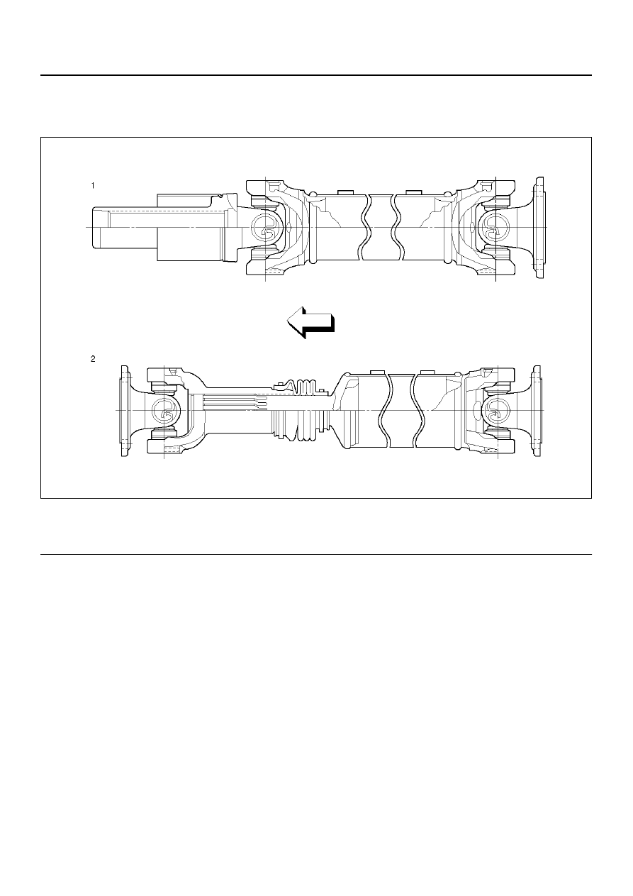
General Description
401RX00005
EndOFCallout
Propeller Shaft
Torque is transmitted from the transmission to the rear
axle through one propeller shaft and universal joint
assemblies. All propeller shafts are the balanced tubular
type. A splined slip joint is provided in some drivelines.
• Since the propeller shaft is balanced carefully,
welding or any other modification are not permitted.
• Alignment marks should be applied to each propeller
shaft before removal.
• Be sure vehicle is stopped, engine is not running,
brake is secured and vehicle is secured to prevent
injury.
• Be careful not to grip the propeller shaft tube too
tightly in the vise as this will be cause deformation.
Phasing
The propeller shaft is designed and built with the yoke
lugs (ears) in line with each other. This design produces
the smoothest running shaft possible, called phasing.
Vibration can be caused by an out-of-phase propeller
shaft. The propeller shaft will absorb vibrations from
speeding up and slowing down each time the universal
joint spins. This vibration would be the same as a
person snapping a rope and watching the "wave"
reaction flow to the end. A propeller shaft working in
phase would be similar to two persons snapping a rope
at the same time, and watching the "waves" meet and
cancel each other out. In comparison, this would be the
same as the universal joints on a propeller shaft. A total
cancellation of vibration produces a smooth flow of
power in the driveline. It is very important to apply a
reference mark to the propeller shaft before removal, to
assure installation alignment.
Legend
(1) For Y22SE 4
´2 M/T Model
(2) For 6VD1 Model and Y22SE 4
´2 A/T Model