Isuzu Amigo / Axiom / Trooper / Rodeo / VehiCross. Manual - part 1740


  Index      Isuzu     Isuzu Amigo / Axiom / Trooper / Rodeo / VehiCross - service repair manual 1999-2002 year


Search            


Content   ..  1738  1739  1740  1741   ..


Isuzu Amigo / Axiom / Trooper / Rodeo / VehiCross. Manual - part 1740


4C–18

DRIVE SHAFT SYSTEM

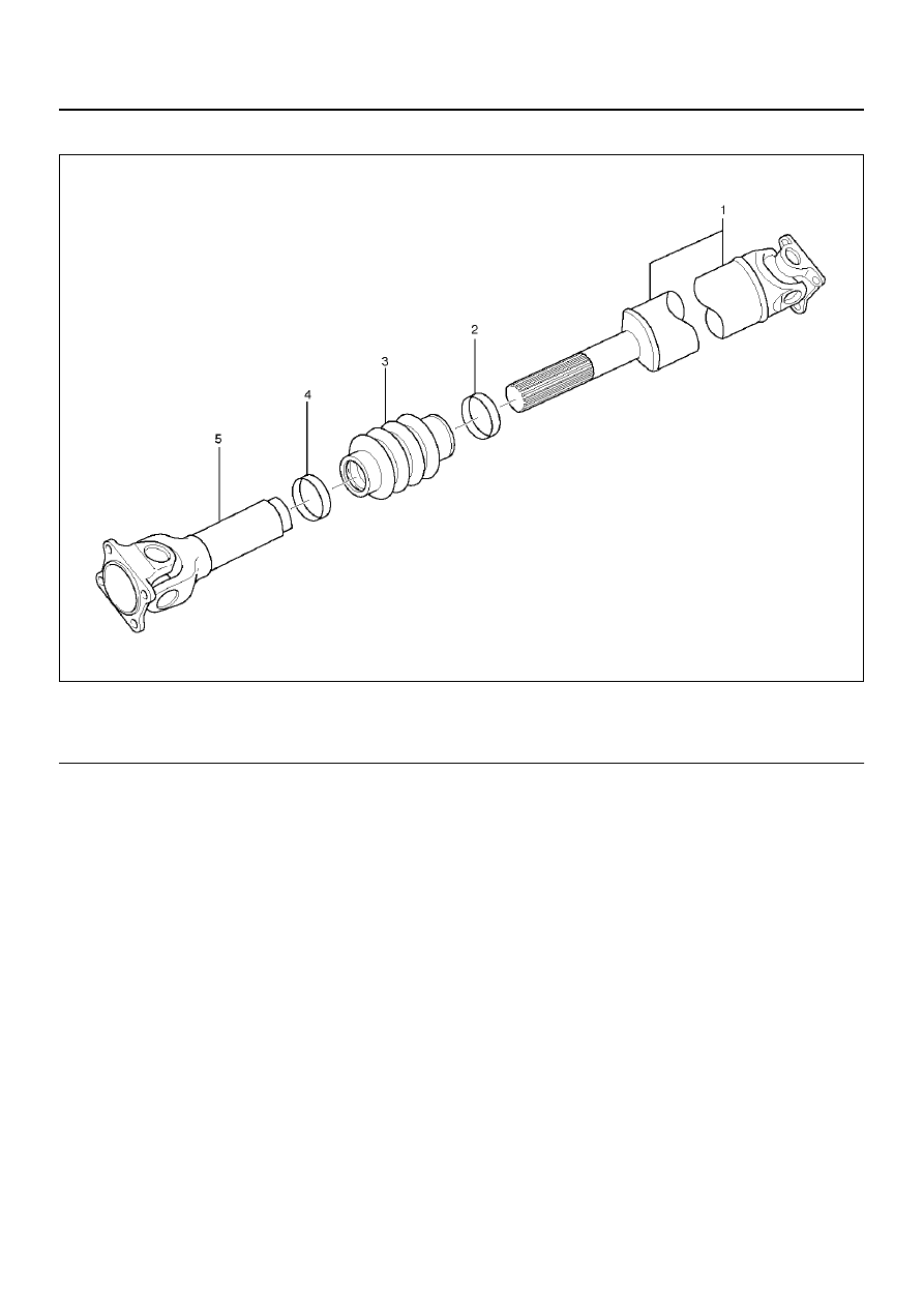
Slip Joint Disassembly (6VD1 Model Only)

401RW081

EndOFCallout

1. Lay the shaft horizontally on a bench and secure.

2. Indicate the original assembled position by marking

the phasing of the shaft prior to disassembly.

3. Using the flat blade of a screwdriver, pry the loose

end of the boot clamp upwards and away from the
propeller shaft boot. Be careful not to damage the
boot.

4. When boot clamps becomes loose, remove by

hand.

5. Repeat for the other boot clamp.

6. Remove the spline yoke assembly from the tube

assembly, by securing the boot with one hand and
pulling on the spline yoke.

7. Remove the boot from the tube assembly.

Legend

(1) Spline Yoke and Universal Joint Assembly
(2) Clamp

(3) Boot
(4) Clamp
(5) Tube and Universal Joint Assembly

DRIVE SHAFT SYSTEM

4C–19

Universal Joint Disassembly

401RX00007

EndOFCallout

Legend

(1) Spline Yoke (Y22SE 4

´2 M/T model)

(2) Spider
(3) Propeller Shaft Assembly
(4) Spider

(5) Flange Yoke
(6) Bearing
(7) Snap Ring
(8) Flange Yoke (6VD1 model and Y22SE 4

´2 A/T 

model)

4C–20

DRIVE SHAFT SYSTEM

1. Apply alignment marks on the yokes of the universal

joint, then remove the snap ring.

401RW076

If the snap ring is stuck in position, remove paint
from the hole in the yoke or tap around the edge of
the bearing lightly with a soft drift.

401RW077

2. Set the yoke in the arbor press with a piece of tube

stock beneath it.
Place a solid plug on the upper bearing and press it
through to release the lower bearing.

401RW079

3. If the bearing will not pull out by hand after pressing,

tap the base of the lug near the bearing to dislodge
it.

4. To remove the opposite bearing, turn the yoke over

and straighten the spider in the open spider hole.
Then carefully press on the end of the spider so the
remaining bearing moves straight out of the bearing
spider hole. If the spider or bearing are cocked, the
bearing will score the walls of the spider hole and
ruin it.

401RW087

DRIVE SHAFT SYSTEM

4C–21

5. Repeat this procedure on the remaining bearing to

remove the spider from the yoke. 

Inspection

• Propeller shaft for runout.

Static runout limit : 0.13 mm(0.005 in)

TIR on the neck of the slip tube shaft (with a
boot).

0.25 mm(0.010 in)

TIR on the ends of the tubing 3 inch from the
welds.

0.38 mm(0.015 in)

TIR at the linear center of the tube.

0.38 mm(0.015 in)

TIR for the full length of tube with 30" or less of
tubing.

TIR: Total Indicator Reading)

401RW017

• Play in universal joint.

Limit: Less than 0.15 mm(0.006in)

• Spider pin should be smooth and free from fretting or

galling.
Visible signs of needle presence is normal, but wear
should not be felt.

• Inspect boot.

Check the boot for crack or damage. If necessary,
replace the boot.
If abnormal condition are found on the boot, inspect
the grease for mixing of foreign material.
If the grease is in good condition, and slip joint works
well, then replace the boot, rplenish the grease, and
reassemble the slip joint.
If the foreign material is found in the grease, then
inspect the spline for wear and damage.

401RW074

• Preload of the universal joint.

Preload should be 0 to 24.9 kg (0 to 11.3 lb).
Joints should rotate smoothly and freely and should
exhibit no rough or ratchety movement.

401RW078

• Inspect splines for wear.

The nylon-coated spline should be free from nicks
and dings and the underlying steel spline should not
be visible.
After cleaning the nylon coating spline, the coating
should exhibit only slight indicator of wear.
Grease volume is approximately 10 grams of grease
in total. Grease should be evenly applied to both the
female and the male slip splines using a small brush.
After assembly of the slip joint, the sliding joint should
be fully worked from the full collapsed to the full
extended position.


Content   ..  1738  1739  1740  1741   ..