Isuzu Amigo / Axiom / Trooper / Rodeo / VehiCross. Manual - part 1737


  Index      Isuzu     Isuzu Amigo / Axiom / Trooper / Rodeo / VehiCross - service repair manual 1999-2002 year


Search            


Content   ..  1735  1736  1737  1738   ..


Isuzu Amigo / Axiom / Trooper / Rodeo / VehiCross. Manual - part 1737


4C–6

DRIVE SHAFT SYSTEM

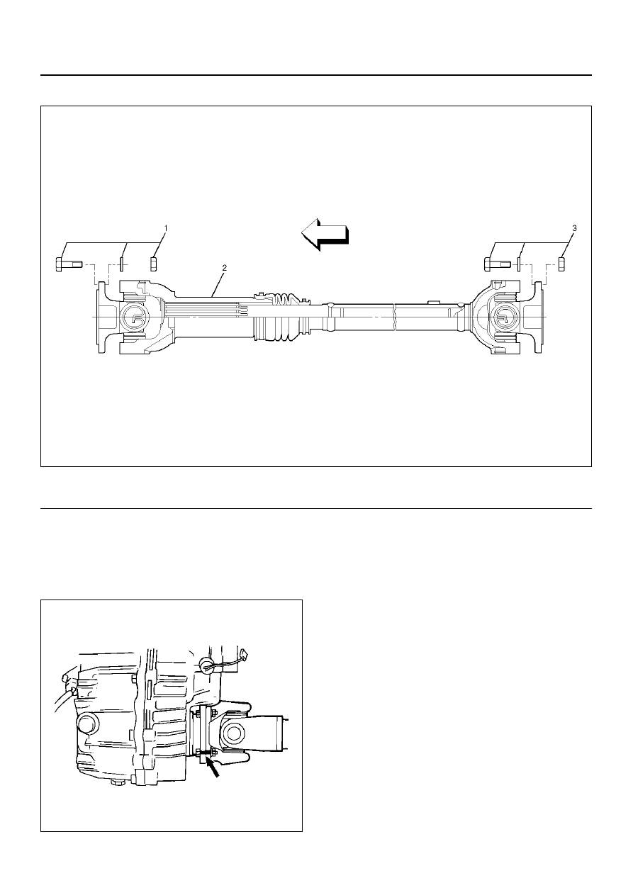
 Front Propeller Shaft and Associated Parts 

401RW093

EndOFCallout

 Removal 

1. Raise the vehicle on a hoist.

NOTE:  Apply alignment marks on the flange at the front
propeller shaft both front and rear side. 

401RS020

2. Remove bolt, nut and washer (Front axle side).

3. Remove bolt, nut and washer (Transfer side).

4. Remove front propeller shaft.

Installation

NOTE:  Never install the shaft assembly backwards.
Never insert bar between yoke lugs when tightening or
removing bolts. Completely remove the black paint from
the connecting surface of flange coupling on each end
of propeller shaft. Clean so that no foreign matter will be
caught in between.

1. Align the mark which is applied at removal. Install

front propeller shaft and tighten the bolts to the
specified torque.

 Torque:63 N·m  (46lb ft) 

Legend

(1) Bolt, Nut and Washer (Front Axle Side)

(2) Front Propeller Shaft (Single Cardan Type)
(3) Bolt, Nut and Washer (Transfer Side)

DRIVE SHAFT SYSTEM

4C–7

Slip Joint Disassembly

401RX00003

EndOFCallout

1. Lay the shaft horizontally on a bench and secure.

2. Indicate the original assembled position (1) by

marking the phasing of the shaft prior to
disassembly.

Legend

(1) Spline Yoke Assembly
(2) Clamp

(3) Boot
(4) Clamp
(5) Tube Assembly

4C–8

DRIVE SHAFT SYSTEM

401RW037

3. Using the flat blade of a screwdriver, pry the loose

end of the boot clamp upwards and away from the
propeller shaft boot. Be careful not to damage the
boot.

4. When boot clamps becomes loose, remove by

hand.

5. Repeat for the other boot clamp.

6. Remove the spline yoke assembly from the tube

assembly, by securing the boot with one hand and
pulling on the spline yoke.

7. Remove the boot from the tube assembly.

 Universal Joint Disassembly (Single Cardan Type)


401RW031

EndOFCallout

Legend

(1) Flange Yoke
(2) Snap Ring

(3) Spider
(4) Needle Roller Bearing

DRIVE SHAFT SYSTEM

4C–9

1. Using a soft drift, tap the outside of the bearing cup

assembly to loosen snap ring. Tap bearing only hard
enough to break assembly away from snap ring.
Remove snap ring from yoke. Turn joint over, tap
bearing away from snap ring, then remove opposite
snap ring.
Apply alignment marks (1) on the yokes of the
universal joint, then remove snap ring.

401RW018

2. Set the yoke in the arbor press with a piece of tube

stock beneath it.
Place a solid plug on the upper bearing assembly
and press it through to release the lower bearing
assembly.

401RW020

3. If the bearing assembly will not pull out by hand

after pressing, tap the base of the lug near the
bearing assembly to dislodge it.

4. To remove the opposite bearing, turn the yoke over

and straighten the spider in the open hole. Then
carefully press on the end of the spider so the
remaining bearing moves straight out of the bearing
spider hole. If the spider or bearing are cocked, the
bearing will score the walls of the spider hole and
ruin the yoke. 

5. Repeat this procedure on the remaining bearing to

remove the spider from the yoke.

6. Make sure of proper position for reinstallation by

applying setting marks, then remove spider .

Spider pin for wear 

Spider pin should be smooth and free from fretting or
galling. Visible signs of needle presence is normal, but
wear should not be felt.

401RW038

 Propeller shaft runout 

Support the propeller shaft on V-blocks (2) and check
for runout by holding the probe of a dial indicator (1) in
contact with the shaft.

Static runout limit:

0.13 mm  (0.005in) 

TIR on the neck of the slip tube shaft (with a
boot).

0.25 mm  (0.010in) 

TIR on the ends of the tubing 3 inch from the
welds.

0.38 mm  (0.015in) 

TIR at the linear center of the tube.

0.38 mm  (0.015in) 

TIR for the full length of tube with 30" or less of
tubing.

(TIR : Total Indicator Reading)


Content   ..  1735  1736  1737  1738   ..