Content .. 1708 1709 1710 1711 ..
Isuzu Amigo / Axiom / Trooper / Rodeo / VehiCross. Manual - part 1710
9J1–51
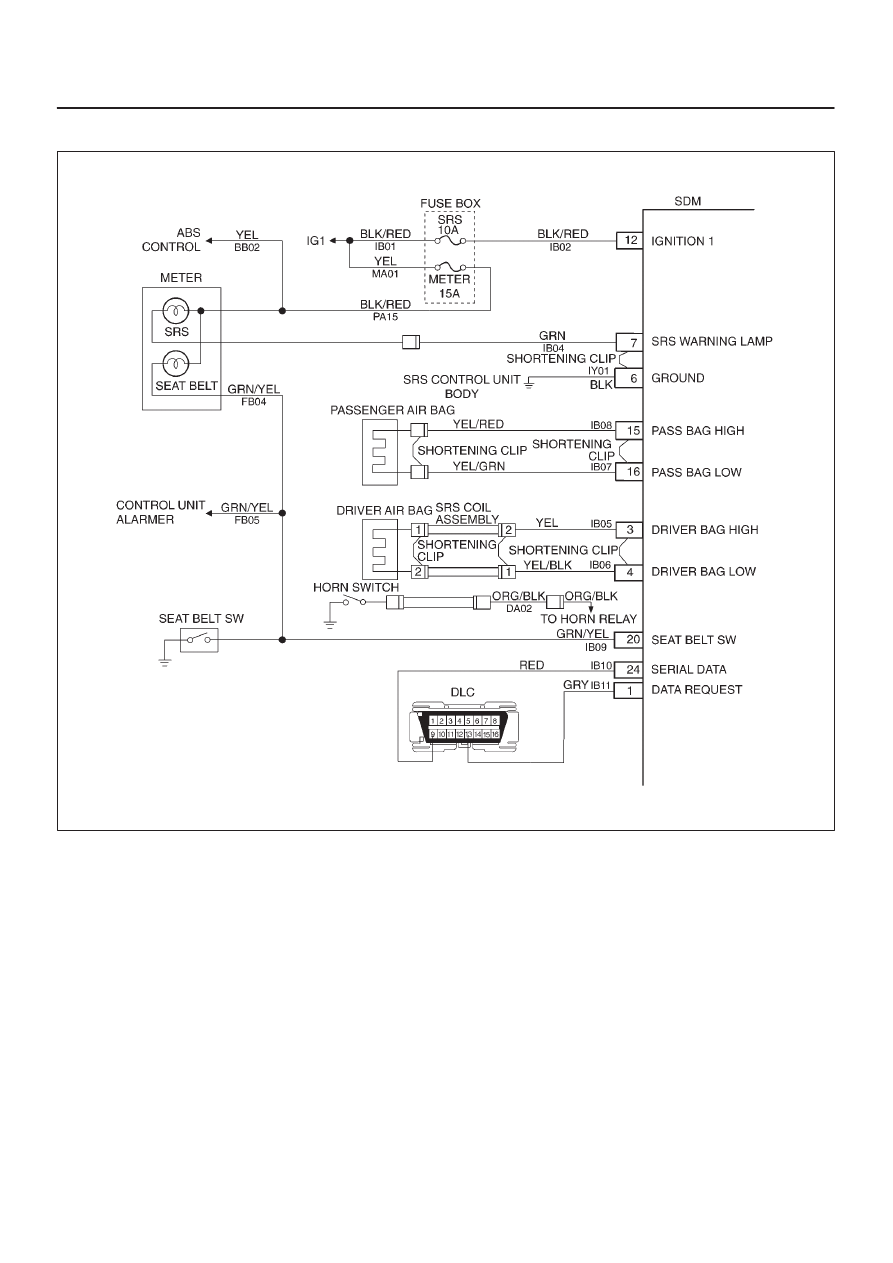
RESTRAINT CONTROL SYSTEM
DTC 61 Warning Lamp Circuit Failure
D09R100002
Circuit Description:
When the ignition switch is turned “ON”, battery voltage is
applied to the “AIR BAG” warning lamp and to the
“ignition 1” input terminal “12”. The Sensing and
Diagnostic Module (SDM) responds by flashing the “AIR
BAG” warning lamp seven times. The SDM monitors the
lamp driver output by comparing the output state at
“Supplemental Restraint System (SRS) warning lamp”
terminal “7” to the microprocessor commanded state.
When “ignition 1” is in the specified value, and the output
state Does not match the commanded state of the lamp
driver for 500 milliseconds, DTC 61 is set.
DTC Will Set When:
“Ignition 1” voltage is in the specified value and the output
state at the “SRS warning lamp” terminal does not match
the commanded state of the lamp driver for 500
milliseconds. This test is run every 100 milliseconds
during “Continuous Monitoring” tests and once per each
ignition cycle at the beginning.
Action Taken:
SDM attempts to turn “ON” the “AIR BAG” warning lamp
and sets a diagnostic trouble code.
DTC Will Clear When:
The ignition switch is turned “OFF.”
Diagnostic Aids:
Refer to
Charts B and C to diagnose warning lamp circuit
malfunctions.