Content .. 1640 1641 1642 1643 ..
Isuzu Amigo / Axiom / Trooper / Rodeo / VehiCross. Manual - part 1642
8F–10
BODY STRUCTURE
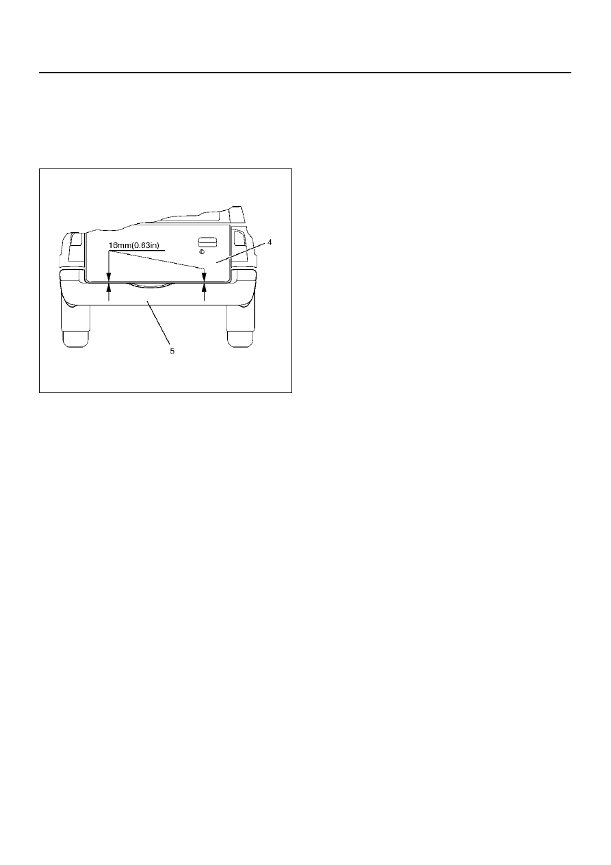
2. Rear bumper adjustment.
• When the bolts fixing rear bumper assembly are
tightened, adjustment should be made with shims
so that clearances shown in the figure below are
provided between the body (tailgate) (4) and the
rear bumper(5).
690RY00014