Isuzu Amigo / Axiom / Trooper / Rodeo / VehiCross. Manual - part 1619


  Index      Isuzu     Isuzu Amigo / Axiom / Trooper / Rodeo / VehiCross - service repair manual 1999-2002 year


Search            


Content   ..  1617  1618  1619  1620   ..


Isuzu Amigo / Axiom / Trooper / Rodeo / VehiCross. Manual - part 1619


LIGHTING SYSTEM

8A–19

Starter Switch

Removal and Installation

Refer to Lock cylinder in steering section.

Lighting Switch (Combination Switch)

Removal and Installation

Refer to Combination Switch in Steering section.

Dimmer·Passing Switch (Combination Switch)

Removal and Installation

Refer to Combination Switch in Steering section.

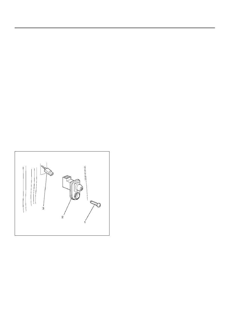
Door Switch

Removal

1. Disconnect the battery ground cable.
2. Remove the door switch (2).

D

Remove the screw (1).

D

Disconnect the connector (3).

825RW289

Installation

To install, follow the removal steps in the reverse order.

8A–20

LIGHTING SYSTEM

Rear Defogger Switch

Removal

1. Disconnect the battery ground cable.
2. Remove the meter cluster assembly (1).

D

Refer to Instrument Panel Assembly in Body
Structure section.

3. Remove the rear defogger switch (2).

D

Disconnect the switch connector.

D

To remove the switch, push the lock from the back
side of the meter cluster assembly.

825RW085

Installation

To install, follow the removal steps in the reverse order.

Key Remind Switch (Starter Switch)

Removal and Installation

Refer to Lock Cylinder in Steering section.

LIGHTING SYSTEM

8A–21

Hazard Warning Light Switch

Removal

1. Disconnect the battery ground cable.
2. Remove the meter cluster assembly (1).

D

Refer to Instrument Panel Assembly in Body
Structure section.

3. Remove the hazard warning switch (2).

D

Disconnect the switch connector.

D

To remove the switch, push the lock from the back
side of the meter cluster assembly.

825RW084

Installation

To install, follow the removal steps in the reverse order.

Stoplight Switch

Removal and Installation

Refer to Stoplight Switch in Brake section.

8A–22

LIGHTING SYSTEM

Backup Light Switch (M/T)

Removal

1. Disconnect the battery ground cable.
2. Remove the backup light switch (1).

D

Disconnect the connector (2).

230RW010

Installation

To install, follow the removal steps in the reverse order,
noting the following point.

1. Apply liquid gasket to the screw portion of the switch

to prevent oil leak.

Turn Signal Light Switch (Combination Switch)

Removal and Installation

Refer to Combination Switch in Steering section.


Content   ..  1617  1618  1619  1620   ..