Content .. 1593 1594 1595 1596 ..
Isuzu Amigo / Axiom / Trooper / Rodeo / VehiCross. Manual - part 1595
7B–16
MANUAL TRANSMISSION
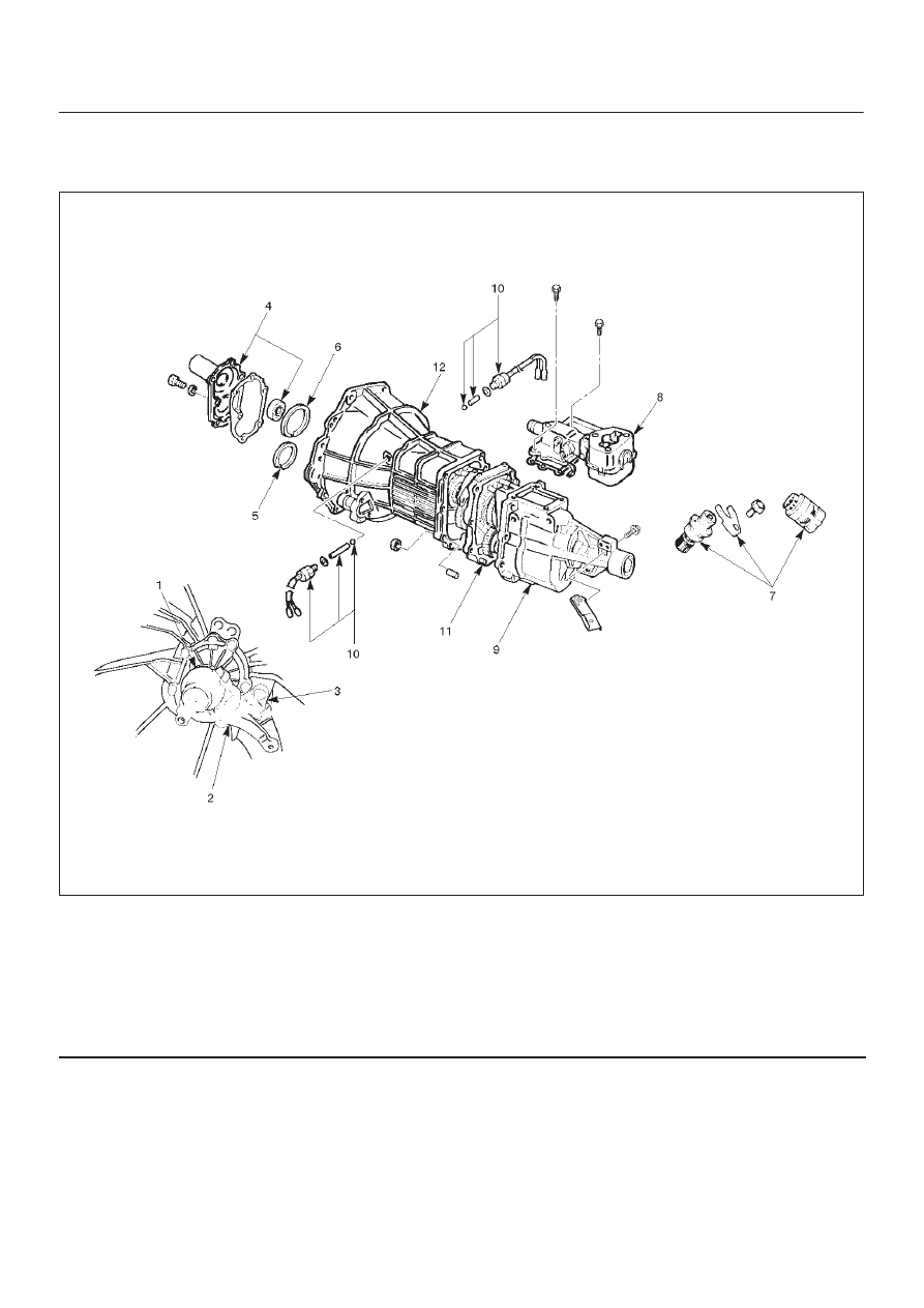
Transmission Case
Major Component (4X2)
220RW050
Legend
(1) Clutch Release Bearing
(2) Shift Fork
(3) Fulcrum Bridge
(4) Front Cover (with Oil Seal)
(5) Counter Front Bearing Snap Ring
(6) Top Gear Bearing Snap Rring
(7) Speedometer Sensor and Speedometer Driven
Gear
(8) Gear Control Box Assembly
(9) Rear Cover with Oil Seal
(10) 1–2 and 3–4 Indicator Switch, Pin, and Ball
(11) Intermediate Plate with Gear Assembly
(12) Transmission Case