Isuzu Amigo / Axiom / Trooper / Rodeo / VehiCross. Manual - part 1553


  Index      Isuzu     Isuzu Amigo / Axiom / Trooper / Rodeo / VehiCross - service repair manual 1999-2002 year


Search            


Content   ..  1551  1552  1553  1554   ..


Isuzu Amigo / Axiom / Trooper / Rodeo / VehiCross. Manual - part 1553


7A–52

AUTOMATIC TRANSMISSION (4L30–E)

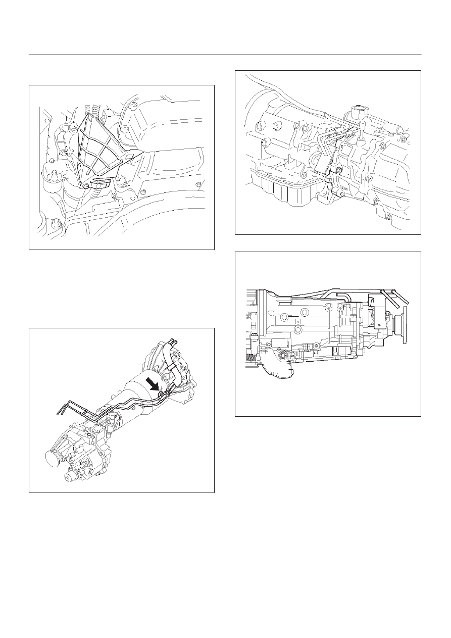
13. Install harness heat protector (V6).

Torque: 6 N

m (52 lb in)

815RW002

14. Connect transmission harness connector and clip.

Connector : Adapter case, mode switch, main case,
magnetic sensor, transfer switch (4

×

4), 2–4 actuator

(4

×

4) and car speed sensor.

15. Connect fuel pipe bracket to transmission side.

NOTE: See “NOTE” of removal steps.

(V6, 4

×

4)

141R100004

(V6, 4

×

4)

240RW014

(V6, 4

×

2)

141RW006

7A–53

AUTOMATIC TRANSMISSION (4L30–E)

(HEC)

253R100002

(HEC)

141R100003

16. Install fuel pipe heat protector and clip.

17. Connector fuel pipe bracket to third crossmember.

141RW004

18. Install center exhaust pipe (V6, 4

×

4).

Torque: 43 N

m (32 lb ft)

150RW008

7A–54

AUTOMATIC TRANSMISSION (4L30–E)

19. Install front propeller shaft (4

×

4) and rear propeller

shaft.

Torque: 63 N

m (46 lb ft)

20. Install transfer protector (4

×

4) and fairing plate (V6).

150RW006

7A–55

AUTOMATIC TRANSMISSION (4L30–E)

Solenoid (Main Case Valve Body)

Removal

1. Raise the vehicle and support it on jack stands.
2. Disconnect battery ground cable.
3. Drain fluid.
4. Remove sixteen 10 mm screws, main case oil pan,

magnet, and gasket.

5. Remove three 13 mm screws, oil filter.
6. Disconnect wiring harness from band control

solenoid and shift solenoids. Pull only on connectors,
not on wiring harness.

7. Remove spring pin for shift solenoid A, shift solenoid

B, and band control solenoid respectively, using
suitable pliers taking care not to damage solenoids.

210RW010

244RW003

8. Remove shift solenoid A, shift solenoid B, band

control solenoid, and gaskets from main case valve
body. Do not pull on wiring harness. Remove
solenoids by grasping the metal tip.

Installation

1. Install shift solenoid A, shift solenoid B, band control

solenoid with new gaskets to main case valve body
respectively.

2. Carefully install spring pin with hammer to avoid

damage to valve body, etc.

243RW004

3. Connect wiring harness to solenoids.
4. Install oil filter with a new gasket and the three 13 mm

screws, tighten to the specified torque.

Torque: 20 N

m (15 lb ft)

5. Install magnet, main case oil pan with new gasket,

and sixteen 10 mm screws. Tighten the screws to the
specified torque.

Torque: 11 N

m (96 lb in)

6. Fill transmission through the overfill screw hole of oil

pan, using ATF DEXRON

–III. Refer to Changing

Transmission Fluid in this section.

7. Connect battery ground cable.


Content   ..  1551  1552  1553  1554   ..