Isuzu Amigo / Axiom / Trooper / Rodeo / VehiCross. Manual - part 153


  Index      Isuzu     Isuzu Amigo / Axiom / Trooper / Rodeo / VehiCross - service repair manual 1999-2002 year


Search            


Content   ..  151  152  153  154   ..


Isuzu Amigo / Axiom / Trooper / Rodeo / VehiCross. Manual - part 153


4D2–26 TRANSFER CASE (TOD)

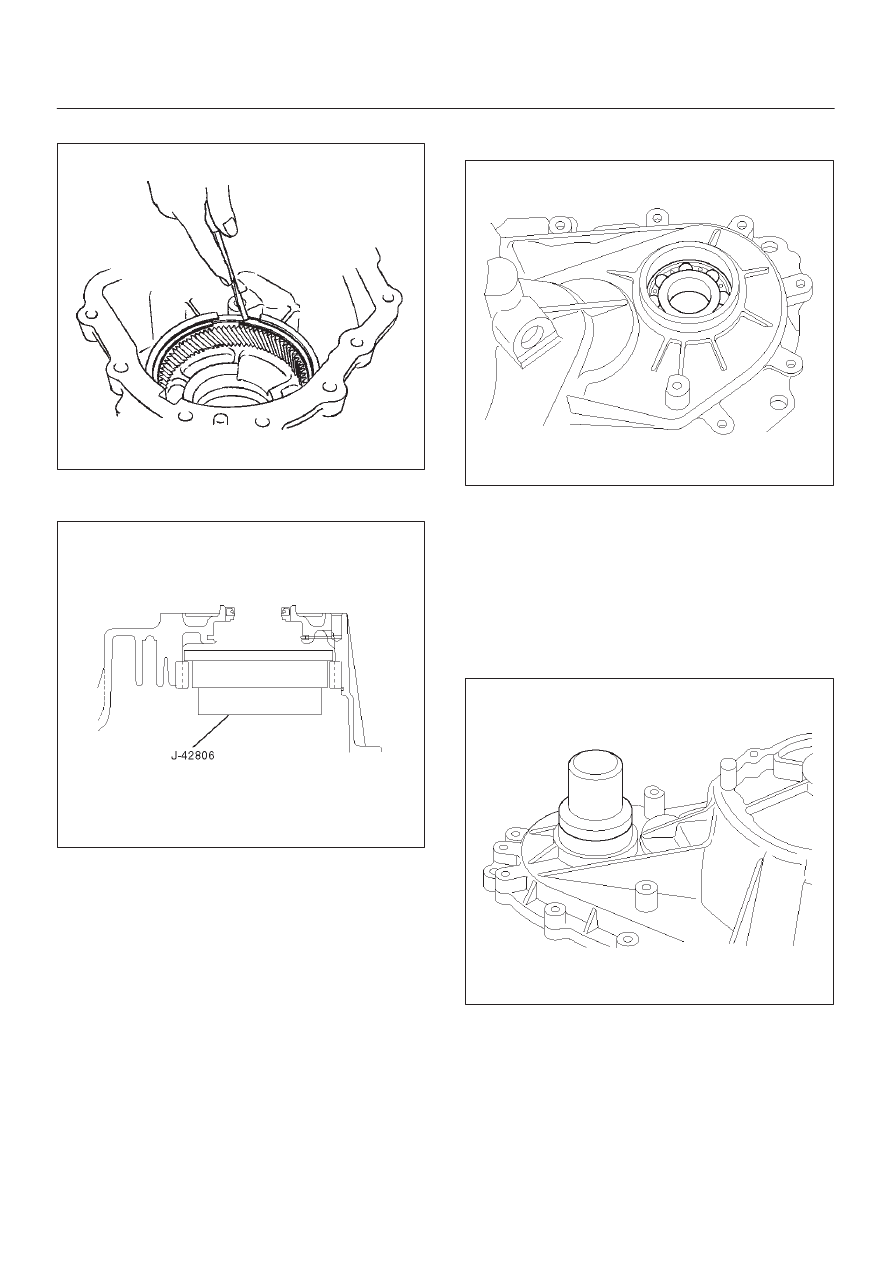
8. Remove the snap ring before the ring gear.

261RW025

9. Using the ring gear remover J–42806 and a bench

press, remove the ring gear from the transfer case.

261R200005

NOTE: Removing ring gear needs a high-load press.
This means the transfer case may be damaged.
To remove and replace the ring gear, it is recommended
that the transfer case assembly should be replaced.

10. Remove the ball bearing of the front output shaft from

the transfer case.

261RY00021

Reassembly

Oil Seal Replacement

1. Remove the oil seal of the front output shaft and input

shaft from the transfer case.

2. Apply the circumference of the new oil seal and fill the

lip with grease (BESCO L2 or its equivalent).

3. Using the oil seal installer J–42807, install the front

output shaft oil seal to the transfer case.

266RY00013

4D2–27

TRANSFER CASE (TOD)

4. Using the oil seal installer J–42808, install the input

shaft oil seal to the transfer case.

261RY00031

5. Using the ring gear installer J–42809 and a bench

press, install the ring gear to the transfer case.

NOTE: Pay attention to the following points.

D

Identify the correct direction of gear.

D

Do not damage the gear.

D

Do not press-fit the ring gear slantingly.

D

Press-fit the ring gear to the innermost.

D

Remove burrs generated by press-fitting.

D

If the transfer case has serrations, match them with
those of the gear and press-fit the gear.

261R200007

6. Install the snap ring.
7. Install the thrust plate to the carrier assembly.

Attach the snap ring to the carrier assembly.

8. Install the carrier assembly to the input shaft.
9. With care the direction of circular hub, mount it to the

input shaft.

265RW008

10. Press the ball bearing to the input shaft so that the

snap ring will be attached to the input shaft.

265RY00004

11. Install the snap ring to the input shaft.

12. Install the ball bearing of the front output shaft to the

transfer case.

4D2–28 TRANSFER CASE (TOD)

13. Install the snap ring of the input shaft bearing to the

transfer case.

265RY00003

14. Using snap ring pliers, open the snap ring from the

gap on the carrier assembly.
While opening the snap ring, securely attach the input
shaft and carrier assembly to the transfer case.

265RY00002

Inspection and Repair (Transfer Case
Assembly)

When wear, damage, or any other defects are observed
during the inspection, the part or parts must be repaired or
replaced. Wash all the parts with clean detergent, and
check that old oil, metallic particles, dirt, or foreign
materials are completely removed. Blow the air into oil
holes and grooves to remove foreign materials or residual
detergent.

Chain

D

Check whether the face that contacts the sprocket is
free from excessive wear or damage. If defects are
observed, replace the part.

D

If the chain interference mark is found on the inside
wall of the transfer cover or the chain is so slack that a
skipped engagement occurs between the chain and
sprocket, replace the chain.

Sprocket

D

Check whether the sprocket tooth surface is
excessively worn or damaged, and there is evidence
of burrs, chipping, wear, or damage on the gear
spline. Remove minor flaws or scratches with oil
stone. If excessive wear or damage is observed,
replace the part.

D

If excessive wear or damage is observed on the
sprocket inside sliding surface, replace the part.

Gear

D

Check whether the gear tooth surface is excessively
worn or damaged, and there is evidence of burrs,
chipping, wear, or damage on the gear spline.
Remove minor flaws or scratches with oil stone. If
excessive wear or damage is observed, replace the
part.

Thickness of Reduction Hub

D

Measure the thickness with a micrometer.

D

If the measurement exceeds the limit, replace the
reduction hub.

Standard : 3.05–3.30 mm (0.120–0.130 in)

Allowable limit : 2.5 mm (0.098 in)

265RW005

4D2–29

TRANSFER CASE (TOD)

Lockup Collar Assembly

D

Install the lockup hub, drive sprocket assembly, and
lockup collar assembly to the output shaft.

D

If the lockup collar assembly does not move
smoothly, replace the lockup collar assembly.

NOTE: Apply ATF to the rear engaging the gear.

Width of Lockup Collar

D

Using calipers, measure the lockup collar groove for
width of wear.

D

If the measurement exceeds the limit, replace the
lockup collar assembly.

Standard : 7.16–7.32 mm (0.282–0.288 in)

Allowable limit : 7.9 mm (0.311 in)

262RY00018

Shift Fork and Rail Assembly

Check the shift fork and rail for wear, distortion, and
scratches. If defects are observed, replace the parts.

Thickness of Shift Fork

D

If the measurement exceeds the limit, replace the
shift fork.

Standard : 3.41–3.79 mm (0.134–0.149 in)

Allowable limit : 4.4 mm (0.173 in)

262RY00016

Lockup Fork and Rail

D

Check the lockup fork and rail for wear, distortion, and
scratches. If defects are observed, replace the parts.

Thickness Lockup Fork

If the measurement exceeds the limit, replace the lockup
fork.

Standard : 6.99–7.09 mm (0.275–0.279 in)

Allowable limit : 6.3 mm (0.248 in)

262RY00017


Content   ..  151  152  153  154   ..