Isuzu Amigo / Axiom / Trooper / Rodeo / VehiCross. Manual - part 151


  Index      Isuzu     Isuzu Amigo / Axiom / Trooper / Rodeo / VehiCross - service repair manual 1999-2002 year


Search            


Content   ..  149  150  151  152   ..


Isuzu Amigo / Axiom / Trooper / Rodeo / VehiCross. Manual - part 151


4D2–18 TRANSFER CASE (TOD)

Reassembly

1. Install the clutch pack assembly which the multi clutch

plate is orderly installed to the output shaft.

NOTE:

D

Install the clutch pack assembly while adjusting the
phase of both the clutch housing and drive sprocket.

D

During installation, the plate of the clutch pack
assembly may slide out of this fixed position (the
correct position is shown in the illustration). If this
occurs, remove all of the clutch plates of the clutch
pack assembly and reinstall them to their correct
position.

266RY00009

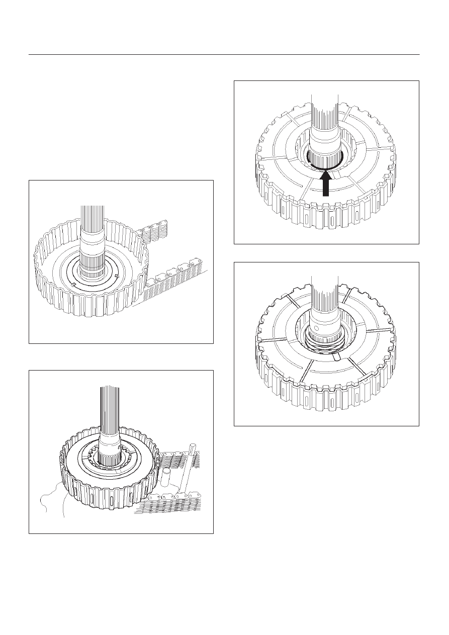
2. Install the insulator washer and armature plate to the

clutch pack assembly.

266RY00008

3. Using snap ring pliers, install the snap ring to the

output shaft.

266RY00007

4. Install the wave spring to the output shaft.

266RY00006

4D2–19

TRANSFER CASE (TOD)

5. Install the cam pulley.
6. Place a ball on each groove of the cam pulley.

266RY00005

7. Install the cam and coil housing to the output shaft.
8. Install the thrust bearing.
9. Install the lockup fork spring.

261RY00020

4D2–20 TRANSFER CASE (TOD)

Chain, Sprocket and Mechanical Lock (Transfer Case Assembly)

262RY00021

Legend

(1) Transfer Case Assembly
(2) Cam and Shaft Rail Assembly
(3) Front Output Shaft
(4) Chain
(5) Lower Drive Sprocket
(6) Front Tone Wheel
(7) Drive Sprocket
(8) Spacer
(9) Shift Fork and Rail Assembly

(10) Lockup Rail

(11) Spring Pin

(12) Shift Fork Assembly
(13) Lockup Fork
(14) Lockup Fork Spring
(15) Reduction Hub
(16) Rear Output Shaft
(17) Oil Pump Assembly (with Strainer)
(18) Thrust Washer
(19) Lockup Hub
(20) Lockup Collar Assembly
(21) Magnet

4D2–21

TRANSFER CASE (TOD)

Disassembly

1. Remove the spacer.
2. Remove the front tone wheel, lower drive sprocket,

drive sprocket and chain together from the front and
rear output shaft.

266RY00010

3. Remove the lockup collar assembly and lockup fork

together.

266RY00011

4. Remove the lockup hub.
5. Remove the thrust washer.

6. Remove the magnet from the strainer set position

together with the oil pump assembly.

266RY00012

7. Remove the output shaft.
8. Remove the cam and shaft rail assembly.

262RY00015

9. Remove the shift fork and rail assembly, and

reduction hub.

10. Remove the spring pin from the shift fork and rail

assembly.

11. Remove the shift fork assembly from the lockup rail.

12. Remove the front output shaft from the transfer case.


Content   ..  149  150  151  152   ..