Isuzu Amigo / Axiom / Trooper / Rodeo / VehiCross. Manual - part 150


  Index      Isuzu     Isuzu Amigo / Axiom / Trooper / Rodeo / VehiCross - service repair manual 1999-2002 year


Search            


Content   ..  148  149  150  151   ..


Isuzu Amigo / Axiom / Trooper / Rodeo / VehiCross. Manual - part 150


4D2–14 TRANSFER CASE (TOD)

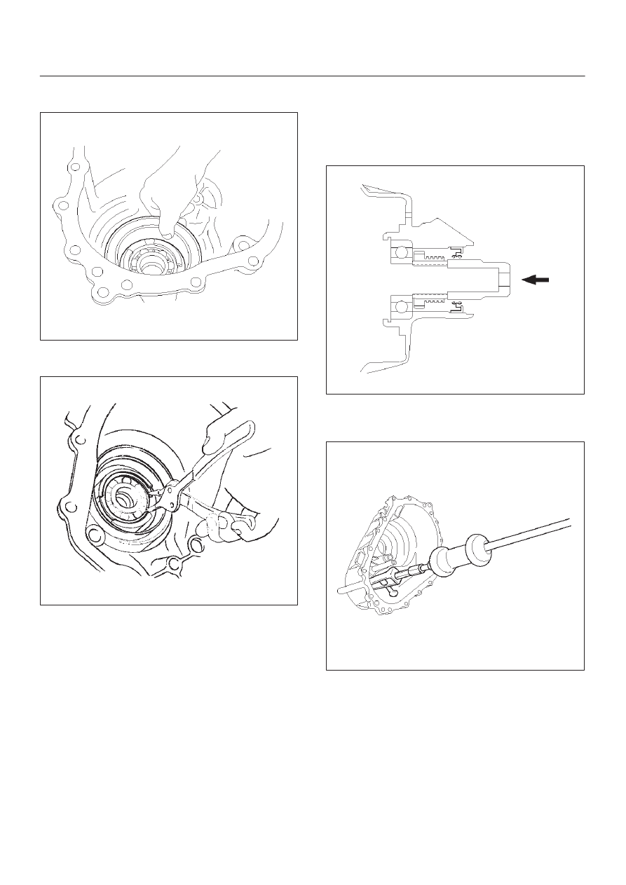
2. Remove the coil assembly set nuts (3 pieces) and coil

assembly from the transfer cover.

261RW030

3. Using snap ring pliers, remove the snap ring from the

transfer cover.

261RW047

4. Strike the speed gear and tone wheel with a rod or

other appropriate tool from the rear side of the
transfer cover assembly, and remove the ball bearing,
speed gear and tone wheel.

NOTE: Use care to prevent damage to the speed gear
teeth.

261RY00012

5. Using the bearing remover J–42805 and slide

hammer J–2619–01, remove the ball bearing of the
front output shaft from the transfer cover.

261RY00027

Inspection and Repair

Refer to 

“Inspection and Repair (Transfer Case

Assembly)” in this section.

4D2–15

TRANSFER CASE (TOD)

Reassembly

Transfer cover oil seal replacement

1. Remove the oil seal from the transfer cover assembly.
2. Apply oil to the circumference of the new oil seal and

fill the lip with grease (BESCO L2 or its equivalent).

3. Using the oil seal installer J–42804, install the oil seal

to the transfer cover assembly.

261RY00017

Shift shaft oil seal replacement

4. Remove the oil seal from the transfer cover assembly.
5. Apply oil the circumference of the new oil seal.
6. Using the oil seal installer J–33951, install the oil seal

to the transfer cover assembly.
The drive in depth must be 9.4 

 10.4 mm (0.370 

0.409 in). The knurled end of the installer (indicated
by the arrow) must be flush with the oil seal
installation surface.

NOTE: Use care to prevent tilt to oil seal when installing
oil seal to the case.

261R200009

7. Install the ball bearing of the front output shaft to the

transfer cover.

8. Install the speed gear and tone wheel.
9. Install the ball bearing to the transfer cover.

10. Using snap ring pliers, install the snap ring to the

transfer cover.

NOTE: The snap ring must be fully inserted into the
transfer cover snap ring groove.

261RY00018

11. Install the coil assembly to the transfer cover and

tighten the set nuts (3 pieces) to the specified torque.

Torque: 10 N·m (87 lb in)

12. Install the connector to the harness terminal of the coil

assembly.

261RY00013

4D2–16 TRANSFER CASE (TOD)

Clutch Pack and Clutch Cam (Transfer Case Assembly)

266RY00015

Legend

(1) Transfer Case Assembly
(2) Snap Ring
(3) Wave Spring
(4) Cam Pulley
(5) Cam Ball

(6) Cam and Coil Housing Assembly
(7) Thrust Bearing
(8) Armature Plate
(9) Insulator Washer

(10) Clutch Pack Assembly

(11) Lockup Fork Spring

Disassembly

1. Remove the lockup fork spring.
2. Remove the thrust bearing and cam and coil housing

assembly from the output shaft.

NOTE: When the cam and coil housing assembly is
removed, the cam balls may be detached together with
the housing. Pay attention not to lose the ball.

261RY00020

4D2–17

TRANSFER CASE (TOD)

3. Remove the cam ball (3 pieces).
4. Remove the cam pulley.

266RY00005

5. Remove the wave spring.

266RY00006

6. Using snap ring pliers, remove the snap ring.

NOTE: Use care to prevent damage to snap ring.

266RY00007

7. Remove the armature plate, insulator washer and

clutch pack assembly as a package.

266RY00008


Content   ..  148  149  150  151   ..