Content .. 1246 1247 1248 1249 ..
Isuzu Amigo / Axiom / Trooper / Rodeo / VehiCross. Manual - part 1248
6E1–68
RODEO Y22SE 2.2L ENGINE DRIVEABILITY AND EMISSION
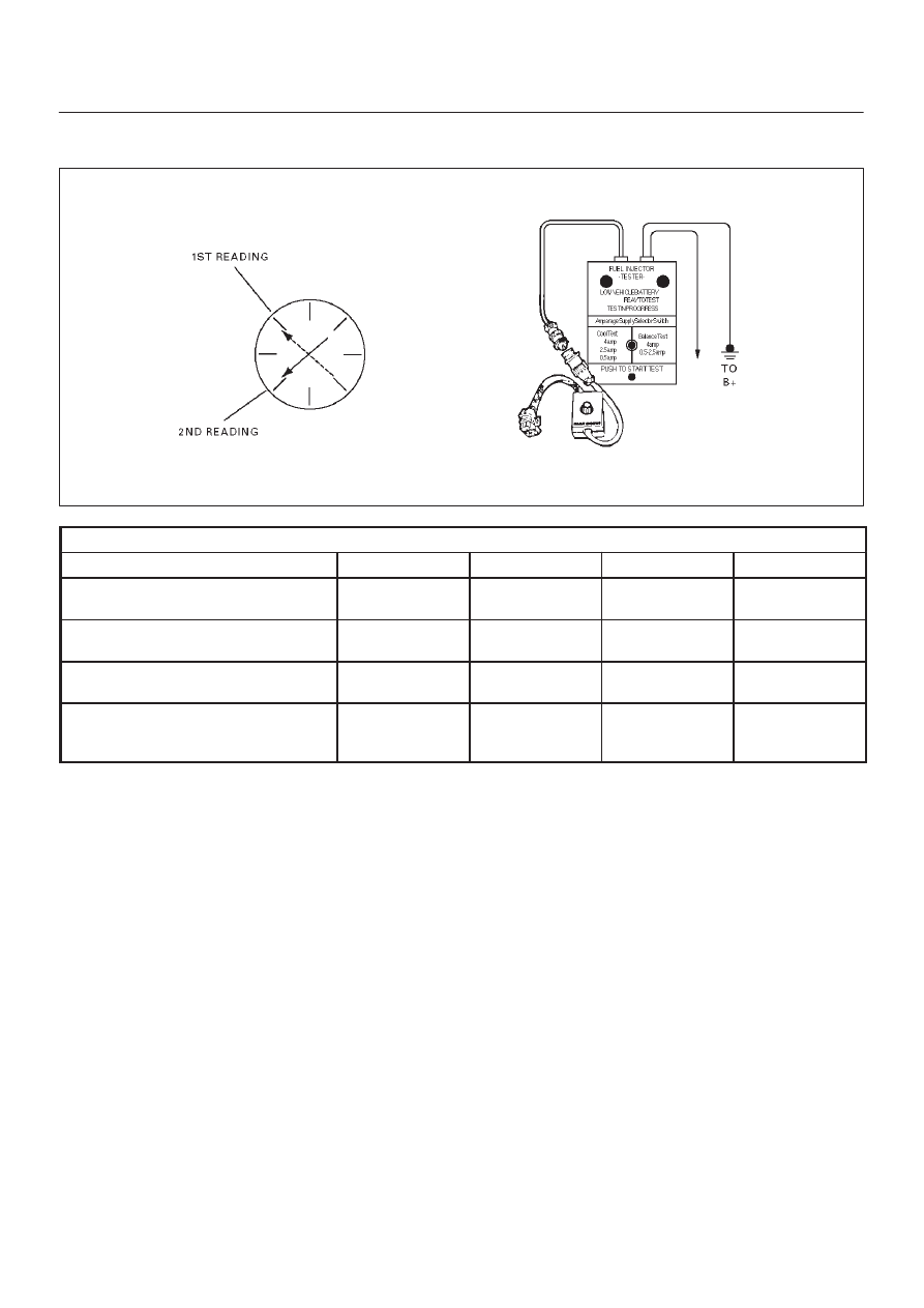
Injector Coil Test Procedure (Steps 1–6)
And Injector Balance Test Procedure (Steps 7–11)
R262001
CYLINDER
1
2
3
4
1st Reading
296 kPa
(43psi)
296 kPa
(43psi)
296 kPa
(43psi)
296 kPa
(43psi)
2nd Reading
131 kPa
(19 psi)
117 kPa
(17 psi)
124 kPa
(18 psi)
145 kPa
(21 psi)
Amount of Drop (1st Reading–2nd
Reading
165 kPa
(24 psi)
179 kPa
(26 psi)
172 kPa
(25 psi)
151 kPa
(22 psi)
Av. drop = 166 kPa/24 psi +/–10
kPa/1.5 psi = 156 – 176 kPa or 22.5
– 25.5 psi
OK
Faulty, Rich
(Too Much Fuel
Drop)
OK
Faulty, Lean
(Too Little Fuel
Drop)
NOTE: These figures are examples only.