Isuzu Amigo / Axiom / Trooper / Rodeo / VehiCross. Manual - part 1246


  Index      Isuzu     Isuzu Amigo / Axiom / Trooper / Rodeo / VehiCross - service repair manual 1999-2002 year


Search            


Content   ..  1244  1245  1246  1247   ..


Isuzu Amigo / Axiom / Trooper / Rodeo / VehiCross. Manual - part 1246


6E1–60

RODEO Y22SE 2.2L ENGINE DRIVEABILITY AND EMISSION

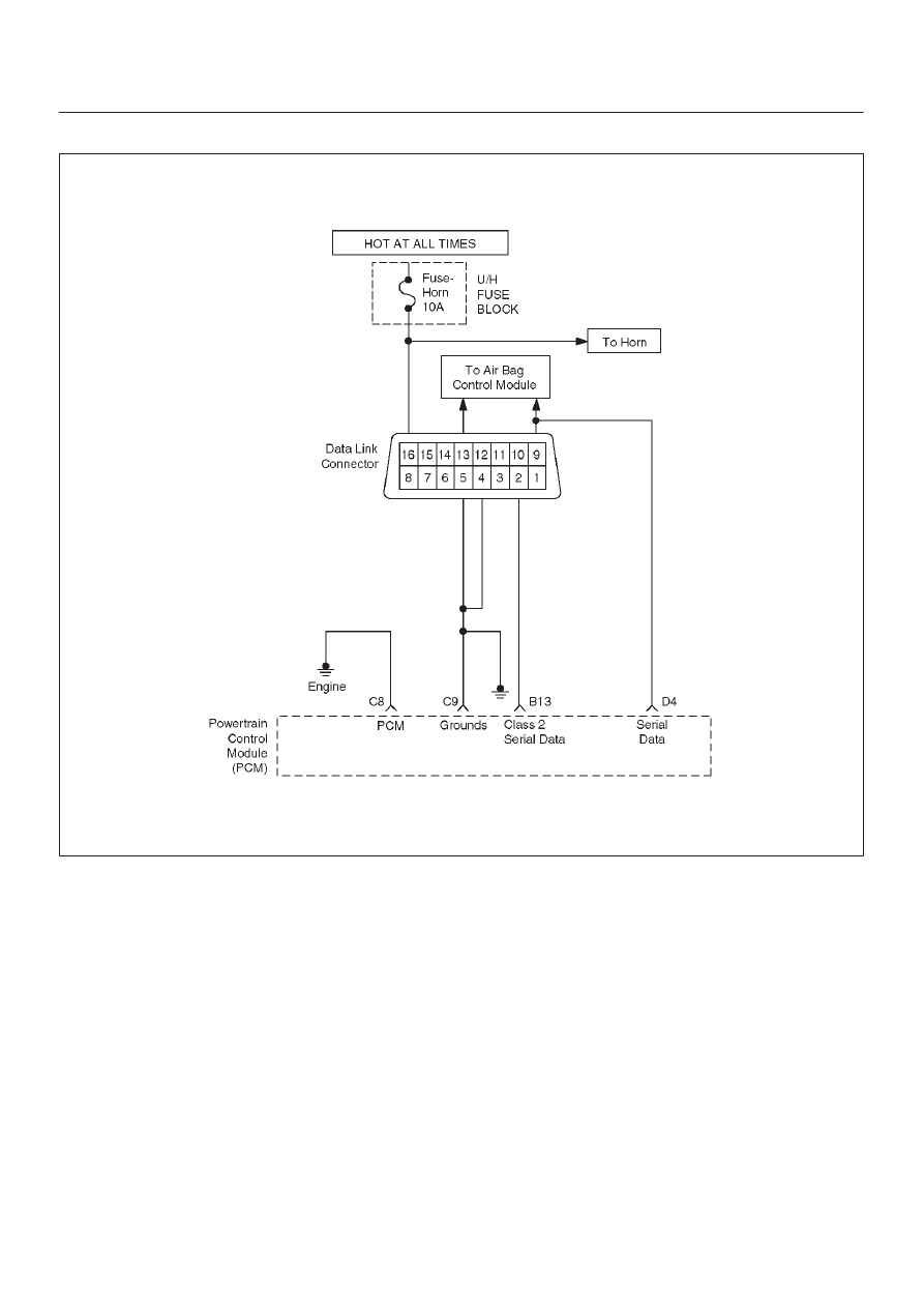
ON–BOARD DIAGNOSTIC (OBD II) SYSTEM CHECK

060R100085

Circuit Description

The on–board diagnostic system check is the starting
point for any driveability complaint diagnosis. Before
using this procedure, perform a careful visual/physical
check of the PCM and engine grounds for cleanliness and
tightness.
The on–board diagnostic system check is an organized
approach to identifying a problem created by an
electronic engine control system malfunction.

Diagnostic Aids

An intermittent may be caused by a poor connection,
rubbed–through wire insulation or a wire broken inside the
insulation. Check for poor connections or a damaged
harness. Inspect the PCM harness and connectors for
improper mating, broken locks, improperly formed or

damaged terminals, poor terminal–to–wire connection,
and damaged harness.

Test Description

Number(s) below refer to the step number(s) on the
Diagnostic Chart:
1. The MIL (”Check Engine” lamp) should be ON

steady with the ignition ON/engine OFF. If not,
isolate the malfunction in the MIL circuit.

2. Checks the Class 2 data circuit and ensures that the

PCM is able to transmit serial data.

3. This test ensures that the PCM is capable of

controlling the MIL and the MIL driver circuit is not
shorted to ground.

 4.  If the engine will not start, the Cranks But Will Not

Run chart should be used to diagnose the condition.

6E1–61

RODEO Y22SE 2.2L ENGINE DRIVEABILITY AND EMISSION

 7.  A Tech 2 parameter which is not within the typical

range may help to isolate the area which is causing
the problem.

10. This vehicle is equipped with a PCM which utilizes

an electrically erasable programmable read only
memory (EEPROM). When the PCM is replaced,
the new PCM must be programmed. Refer to PCM
Replacement and Programming Procedures in
Powertrain Control Module (PCM) and Sensors.

On–Board Diagnostic (OBD II) System Check


Step

Action

Value(s)

Yes

No

1

1. Ignition ON, engine OFF.
2. Observe the malfunction indicator lamp (MIL or

”Check Engine lamp”).

Is the MIL (”Check Engine lamp”) ON?

Go to 

Step 2

Go to 

No MIL

2

1. Ignition OFF.
2. Install a Tech 2.
3. Ignition ON.
4. Attempt to display PCM engine data with the Tech 2.

Does the Tech 2 display PCM data?

Go to 

Step 3

Go to 

Step 8

3

1. Using the Tech 2 output tests function, select MIL

dash lamp control and command the MIL OFF.

2. Observe the MIL.

Did the MIL turn OFF?

Go to 

Step 4

Go to MIL

(”Check

Engine

Lamp”) On

Steady

4

Attempt to start the engine.

Did the engine start and continue to run?

Go to 

Step 5

Go to 

Cranks

But Will Not

Run

5

Select ”Display DTCs” with the Tech 2.

Are any DTCs stored?

Go to 

Step 6

Go to 

Step 7

6

Are two or more of the following DTCs stored? P0107,
P0113, P0118, P0122, P0123.

Go to

“Multiple

PCM

Information

Sensor DTCs

Set”

Go to

applicable
DTC table

7

Compare PCM data values displayed on the Tech 2 to
the typical engine scan data values.

Are the displayed values normal or close to the typical
values?

Go to 

“Typial

Scan” Data

Value

Go to

indicated

Component

System
Checks

8

1. Ignition OFF, disconnect the PCM.
2. Ignition ON, engine OFF.
3. Check the Class 2 data circuit for an open, short to

ground, or short to voltage. Also, check the DLC
ignition feed circuit for an open or short to ground
and the DLC ground circuits for an open.

4. If a problem found, repair as necessary.

Was a problem found?

Go to 

Step 2

Go to 

Step 9

6E1–62

RODEO Y22SE 2.2L ENGINE DRIVEABILITY AND EMISSION

On–Board Diagnostic (OBD II) System Check

  (Cont'd)

Step

No

Yes

Value(s)

Action

9

1. Attempt to reprogram the PCM. Refer to Powertrain

Control Module (PCM) in On–Vehicle Service.

2. Attempt to display PCM data with the Tech 2.

Does the Tech 2 display PCM engine data?

Go to 

Step 2

Go to 

Step 10

10

Replace the PCM.

IMPORTANT: The replacement PCM must be
programmed. Refer to Powertrain Control Module
(PCM) in On–Vehicle Service.

And also refer to latest service bulletin
Check to see if the Latest software is released or not.
And then Down Load the LATEST PROGRAMMED
SOFTWARE to the replacement PCM.

Is the action complete?

Verify repair

6E1–63

RODEO Y22SE 2.2L ENGINE DRIVEABILITY AND EMISSION

A/C CLUTCH CONTROL CIRCUIT DIAGNOSIS

060R100022

Circuit Description

When air conditioning and blower fan are selected, and if
the system has a sufficient refrigerent charge, a 12–volt
signal is supplied to the A/C request input of the
powertrain control module (PCM). The A/C request signal
may be temporarily cancelled during system operation by
the electronic thermostat in the evaporator case. The
electronic thermostat may intermittently remove the
control circuit ground for the A/C thermostat relay to
prevent the evaporator from forming ice. When the A/C
request signal is received by the PCM, the PCM supplies
a ground from the compressor clutch relay if the engine
operating conditions are within acceptable ranges. With
the A/C compressor relay energized, battery voltage is
supplied to the compressor clutch coil.
The PCM will enable the compressor clutch to engage
whenever A/C has been selected with the engine running,
unless any of the following conditions are present:

D

The throttle is greater than 90%.

D

The ignition voltage is below 10.5 volts.

D

The engine speed is greater than 4500 RPM for 5
seconds or 5400 RPM.

D

The engine coolant temperature (ECT) is greater
than 125

°

C (257

°

F)

D

The intake air temperature (IAT) is less than 5

°

C

(41

°

F).

D

The power steering pressure switch signals a high
pressure condition position.

Diagnostic Aids

To diagnose an intermittent fault, check for the following
conditions:

D

Poor connection at the PCM – Inspect harness
connections for backed–out terminals, improper
mating, broken locks, improperly formed or damaged
terminals, and poor terminal–to–wire connection.


Content   ..  1244  1245  1246  1247   ..