Isuzu Amigo / Axiom / Trooper / Rodeo / VehiCross. Manual - part 1245


  Index      Isuzu     Isuzu Amigo / Axiom / Trooper / Rodeo / VehiCross - service repair manual 1999-2002 year


Search            


Content   ..  1243  1244  1245  1246   ..


Isuzu Amigo / Axiom / Trooper / Rodeo / VehiCross. Manual - part 1245


6E1–56

RODEO Y22SE 2.2L ENGINE DRIVEABILITY AND EMISSION

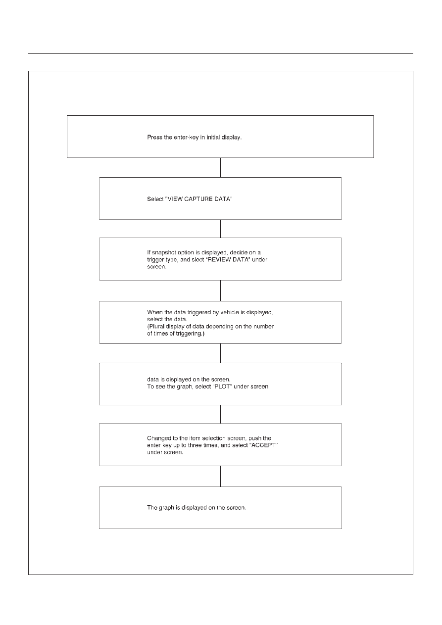
Flow Chart for Snapshot Replay (Plotting Graph)

060RX040

6E1–57

RODEO Y22SE 2.2L ENGINE DRIVEABILITY AND EMISSION

PRIMARY SYSTEM–BASED

DIAGNOSTICS

Primary System–Based Diagnostics

There are primary system–based diagnostics which
evaluate system operation and its effect on vehicle
emissions. The primary system–based diagnostics are
listed below with a brief description of the diagnostic
function:

Oxygen Sensor Diagnosis
The fuel control heated oxygen sensor (HO2S 1) is
diagnosed for the following conditions:

D

Heater performance (time to activity on cold start)

D

Slow response

D

Response time (time to switch R/L or L/R)

D

Inactive signal (output steady at bias voltage –
approx. 450 mV)

D

Signal fixed high

D

Signal fixed low

The catalyst monitor heated oxygen sensor (HO2S 2) is
diagnosed for the following conditions:

D

Heater performance (time to activity on cold start).

D

Signal fixed low during steady state conditions or
power enrichment (hard acceleration when a rich
mixture should be indicated).

D

Signal fixed high during steady state conditions or
deceleration mode (deceleration when a lean mixture
should be indicated).

D

Inactive sensor (output steady at approx. 438 mV).

If the oxygen sensor pigtail wiring, connector or terminal
are damaged, the entire oxygen sensor assembly must
be replaced. DO NOT attempt to repair the wiring,
connector or terminals. In order for the sensor to function
properly, it must have clean reference air provided to it.
This clean air reference is obtained by way of the oxygen
sensor wire(s). Any attempt to repair the wires, connector
or terminals could result in the obstruction of the
reference air and degrade oxygen sensor performance.
Refer to On–Vehicle Service, Heated Oxygen Sensors.

Fuel Control Heated Oxygen Sensors 

The main function of the fuel control heated oxygen
sensors is to provide the control module with exhaust
stream oxygen content information to allow proper fueling
and maintain emissions within mandated levels. After it
reaches operating temperature, the sensor will generate
a voltage, inversely proportional to the amount of oxygen
present in the exhaust gases. The control module uses
the signal voltage from the fuel control heated oxygen
sensors while in ”Closed Loop” to adjust fuel injector
pulse width. While in ”Closed Loop”, the PCM can adjust
fuel delivery to maintain an air/fuel ratio which allows the
best combination of emission control and driveability. The
fuel control heated oxygen sensors are also used to
determine catalyst efficiency.

HO2S Heater

Heated oxygen sensors are used to minimize the amount
of time required for ”Closed Loop” fuel control to begin
operation and to allow accurate catalyst monitoring. The
oxygen sensor heater greatly decreases the amount of
time required for fuel control sensor (HO2S 1) to become
active. Oxygen sensor heaters are required by the
catalyst monitor sensor (HO2S 2) to maintain a
sufficiently high temperature which allows accurate
exhaust oxygen content readings further away from the
engine.

Catalyst Monitor Heated Oxygen Sensors
And Diagnostic Operation 

TS24067

To control emissions of hydrocarbons (HC), carbon
monoxide (CO), and oxides of nitrogen (NOx), a
three–way catalytic converter is used. The catalyst within
the converter promotes a chemical reaction which
oxidizes the HC and CO present in the exhaust gas,
converting them into harmless water vapor and carbon
dioxide. The catalyst also reduces NOx, converting it to
nitrogen. The PCM has the ability to monitor this process
using the pre–catalyst and post–catalyst heated oxygen
sensors. The pre–catalyst sensor produces an output
signal which indicates the amount of oxygen present in
the exhaust gas entering the three–way catalytic
converter. The post–catalyst sensor produces an output
signal which indicates the oxygen storage capacity of the
catalyst; this in turn indicates the catalyst’s ability to
convert exhaust gases efficiently. If the catalyst is
operating efficiently, the pre–catalyst signal will be far
more active than that produced by the post–catalyst
sensor.
In addition to catalyst monitoring, the heated oxygen
sensors have a limited role in controlling fuel delivery. If
the sensor signal indicates a high or low oxygen content
for an extended period of time while in ”Closed Loop”, the
PCM will adjust the fuel delivery slightly to compensate.

D

For the 2.2L engine, the pre–catalyst monitor sensor
is designated Bank 1 HO2S 1. The post–catalyst
sensor is Bank 1 HO2S 2.

6E1–58

RODEO Y22SE 2.2L ENGINE DRIVEABILITY AND EMISSION

Catalyst Monitor Outputs
The catalyst monitor diagnostic is sensitive to the
following conditions:

D

Exhaust leaks

D

HO2S contamination

D

Alternate fuels

Exhaust system leaks may cause the following:

D

Preventing a degraded catalyst from failing the
diagnostic.

D

Causing a false failure for a normally functioning
catalyst.

D

Preventing the diagnostic from running.

Some of the contaminants that may be encountered are
phosphorus, lead, silica, and sulfur. The presence of
these contaminants will prevent the TWC diagnostic from
functioning properly.

Three–Way Catalyst Oxygen Storage Capacity
The Three–Way catalyst (TWC) must be monitored for
efficiency. To accomplish this, the control module
monitors the pre–catalyst HO2S and post–catalyst HO2S
oxygen sensors. When the TWC is operating properly,
the post–catalyst oxygen sensor will have significantly
less activity than the pre–catalyst oxygen sensor. The
TWC stores and releases oxygen as needed during its
normal reduction and oxidation process. The control
module will calculate the oxygen storage capacity using
the difference between the pre–catalyst and post catalyst
oxygen sensor’s voltage levels. If the activity of the
post–catalyst oxygen sensor approaches that of the
pre–catalyst oxygen sensor, the catalyst’s efficiency is
degraded.
Stepped or staged testing level allow the control module
to statistically filter test information. This prevents falsely
passing or falsely failing the oxygen storage capacity test.
The calculations performed by the on–board diagnostic
system are very complex. For this reason, post catalyst
oxygen sensor activity should not be used to determine
oxygen storage capacity unless directed by the service
manual.
Two stages are used to monitor catalyst efficiency.
Failure of the first stage will indicate that the catalyst
requires further testing to determine catalyst efficiency.
The second stage then looks at the inputs from the pre
and post catalyst HO2S sensors more closely before
determining if the catalyst is indeed degraded. This
further statistical processing is done to increase the
accuracy of oxygen storage capacity type monitoring.
Failing the first (stage 1) test DOES NOT indicate a failed
catalyst. The catalyst may be marginal or the fuel sulfur
content could be very high.
Aftermarket HO2S characteristics may be different from
the original equipment manufacturer sensor. This may
lead to a false pass or a false fail of the catalyst monitor
diagnostic. Similarly, if an aftermarket catalyst does not
contain the same amount of cerium as the original part,
the correlation between oxygen storage and conversion
efficiency may be altered enough to set a false DTC.

MISFIRE MONITOR 

DIAGNOSTIC OPERATION

Misfire Monitor Diagnostic Operation

The misfire monitor diagnostic is based on crankshaft
rotational velocity (reference period) variations. The PCM
determines crankshaft rotational velocity using the
crankshaft position sensor and camshaft position sensor.
When a cylinder misfires, the crankshaft slows down
momentarily. By monitoring the crankshaft and camrhaft
position sensor signals, the PCM can calculate when a
misfire occurs.
For a non–catalyst damaging misfire, the diagnostic will
be required to monitor a misfire present for between
1000–3200 engine revolutions.
For catalyst–damaging misfire, the diagnostic will
respond to misfire within 200 engine revolutions.
Rough roads may cause false misfire detection. A rough
road will cause torque to be applied to the drive wheels
and drive train. This torque can intermittently decrease
the crankshaft rotational velocity. This may be falsely
detected as a misfire.

Misfire Counters

Whenever a cylinder misfires, the misfire diagnostic
counts the misfire and notes the crankshaft position at the
time the misfire occurred. These ”misfire counters” are
basically a file on each engine cylinder. A current and a
history misfire counter are maintained for each cylinder.
The misfire current counters (Misfire Cur #1–4) indicate
the number of firing events out of the last 200 cylinder
firing events which were misfires. The misfire current
counter will display real time data without a misfire DTC
stored. The misfire history counters (Misfire Hist#1–4)
indicate the total number of cylinder firing events which
were misfires. The misfire history counters will display 0
until the misfire diagnostic has failed and a DTC P0300 is
set. Once the misfire DTC P0300 is set, the misfire history
counters will be updated every 200 cylinder firing events.
A misfire counter is maintained for each cylinder.
If the misfire diagnostic reports a failure, the diagnostic
executive reviews all of the misfire counters before
reporting a DTC. This way, the diagnostic executive
reports the most current information.
When crankshaft rotation is erratic, a misfire condition will
be detected. Because of this erratic condition, the data
that is collected by the diagnostic can sometimes
incorrectly identify which cylinder is misfiring.
Use diagnostic equipment to monitor misfire counter data
on OBD II–compliant vehicles. Knowing which specific
cylinder(s) misfired can lead to the root cause, even when
dealing with a multiple cylinder misfire. Using the
information in the misfire counters, identify which
cylinders are misfiring. If the counters indicate cylinders
numbers 1 and 4 misfired, look for a circuit or component
common to both cylinders number 1 and 4.
Misfire counter information is located in the ”Specific
Eng.” menu, ”Misfire Data” sub–menu of the data list.
The misfire diagnostic may indicate a fault due to a
temporary fault not necessarily caused by a vehicle

6E1–59

RODEO Y22SE 2.2L ENGINE DRIVEABILITY AND EMISSION

emission system malfunction. Examples include the
following items:

D

Contaminated fuel

D

Low fuel

D

Fuel–fouled spark plugs

D

Basic engine fault

FUEL TRIM SYSTEM 

MONITOR DIAGNOSTIC OPERATION

Fuel Trim System Monitor Diagnostic
Operation

This system monitors the averages of short–term and
long–term fuel trim values. If these fuel trim values stay at
their limits for a calibrated period of time, a malfunction is
indicated. The fuel trim diagnostic compares the
averages of short–term fuel trim values and long–term
fuel trim values to rich and lean thresholds. If either value
is within the thresholds, a pass is recorded. If both values
are outside their thresholds, a rich or lean DTC will be
recorded.
The fuel trim system diagnostic also conducts an intrusive
test. This test determines if a rich condition is being
caused by excessive fuel vapor from the EVAP canister.
In order to meet OBD II requirements, the control module
uses weighted fuel trim cells to determine the need to set
a fuel trim DTC. A fuel trim DTC can only be set if fuel trim
counts in the weighted fuel trim cells exceed
specifications. This means that the vehicle could have a
fuel trim problem which is causing a problem under
certain conditions (i.e., engine idle high due to a small
vacuum leak or rough idle due to a large vacuum leak)
while it operates fine at other times. No fuel trim DTC
would set (although an engine idle speed DTC or HO2S
DTC may set). Use the Tech 2 to observe fuel trim counts
while the problem is occurring.
A fuel trim DTC may be triggered by a number of vehicle
faults. Make use of all information available (other DTCs
stored, rich or lean condition, etc.) when diagnosing a fuel
trim fault.

Fuel Trim Cell Diagnostic Weights

No fuel trim DTC will set regardless of the fuel trim counts
in cell 0 unless the fuel trim counts in the weighted cells
are also outside specifications. This means that the
vehicle could have a fuel trim problem which is causing a
problem under certain conditions (i.e. engine idle high due
to a small vacuum leak or rough due to a large vacuum
leak) while it operates fine at other times. No fuel trim DTC
would set (although an engine idle speed DTC or HO2S
DTC may set). Use the Tech 2 to observe fuel trim counts
while the problem is occurring.


Content   ..  1243  1244  1245  1246   ..