Content .. 1247 1248 1249 1250 ..
Isuzu Amigo / Axiom / Trooper / Rodeo / VehiCross. Manual - part 1249
6E1–72
RODEO Y22SE 2.2L ENGINE DRIVEABILITY AND EMISSION
POWERTRAIN CONTROL MODULE
(PCM) DIAGNOSIS
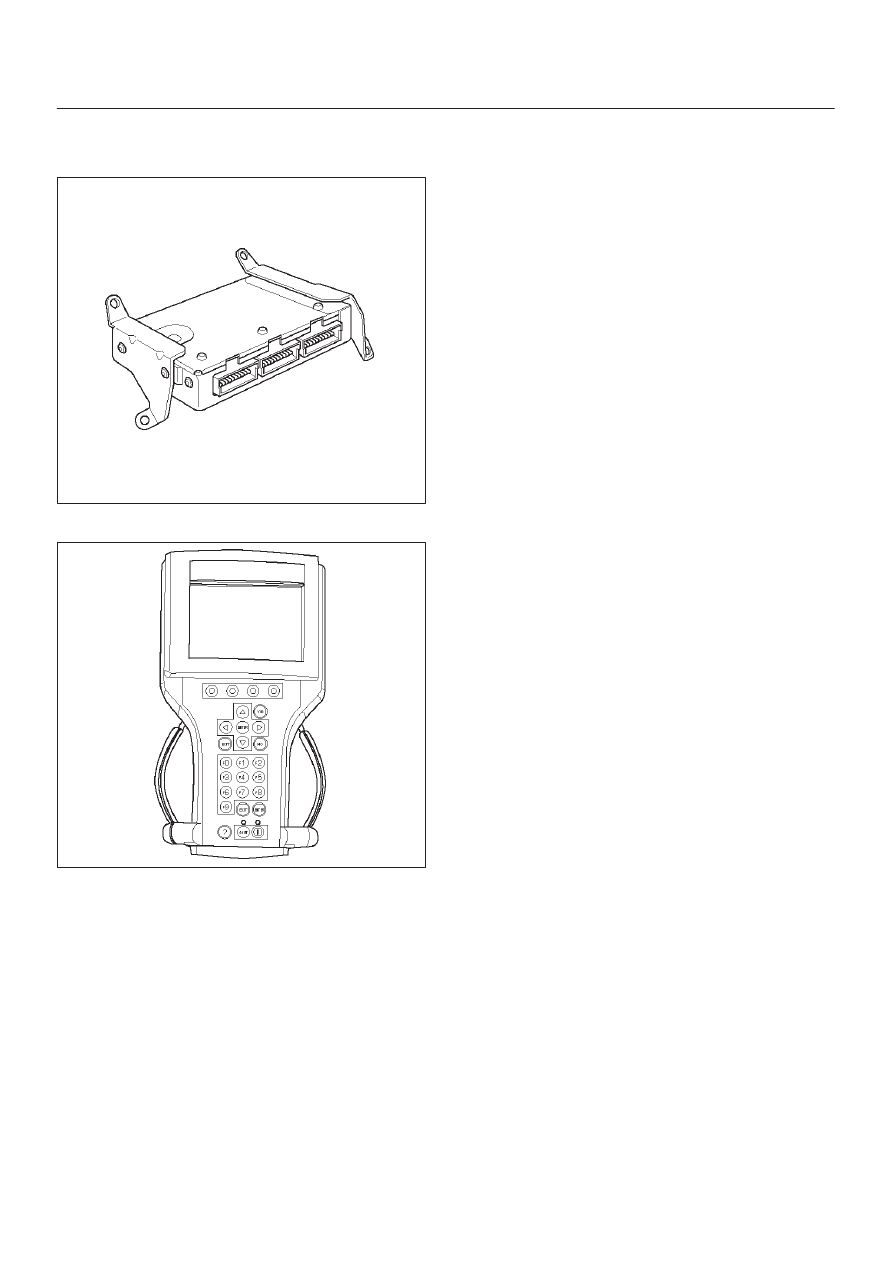
014RX002
To read and clear diagnostic trouble codes, use a Tech 2.
901RX031
IMPORTANT:
Use of a Tech 2 is recommended to clear
diagnostic trouble codes from the PCM memory.
Diagnostic trouble codes can also be cleared by turning
the ignition OFF and disconnecting the battery power
from the PCM for 30 seconds. Turning off the ignition and
disconnecting the battery power from the PCM will cause
all diagnostic information in the PCM memory to be
cleared. Therefore, all the diagnostic tests will have to be
re–run.
Since the PCM can have a failure which may affect only
one circuit, following the diagnostic procedures in this
section will determine which circuit has a problem and
where it is.
If a diagnostic chart indicates that the PCM connections
or the PCM is the cause of a problem, and the PCM is
replaced, but this does not correct the problem, one of the
following may be the reason:
D
There is a problem with the PCM terminal
connections. The terminals may have to be removed
from the connector in order to check them properly.
D
EEPROM program is not correct for the application.
Incorrect components or reprogramming the PCM
with the wrong EEPROM program may cause a
malfunction and may or may not set a DTC.
D
The problem is intermittent. This means that the
problem is not present at the time the system is being
checked. In this case, make a careful physical
inspection of all components and wiring associated
with the affected system and refer to the Symptoms
portion of the manual.
D
There is a shorted solenoid, relay coil, or harness.
Solenoids and relays are turned ON and OFF by the
PCM using internal electronic switches called drivers.
A shorted solenoid, relay coil, or harness will not
damage the PCM but will cause the solenoid or relay
to be inoperative.