Isuzu Amigo / Axiom / Trooper / Rodeo / VehiCross. Manual - part 1176


  Index      Isuzu     Isuzu Amigo / Axiom / Trooper / Rodeo / VehiCross - service repair manual 1999-2002 year


Search            


Content   ..  1174  1175  1176  1177   ..


Isuzu Amigo / Axiom / Trooper / Rodeo / VehiCross. Manual - part 1176


BRAKE CONTROL SYSTEM

5A–33

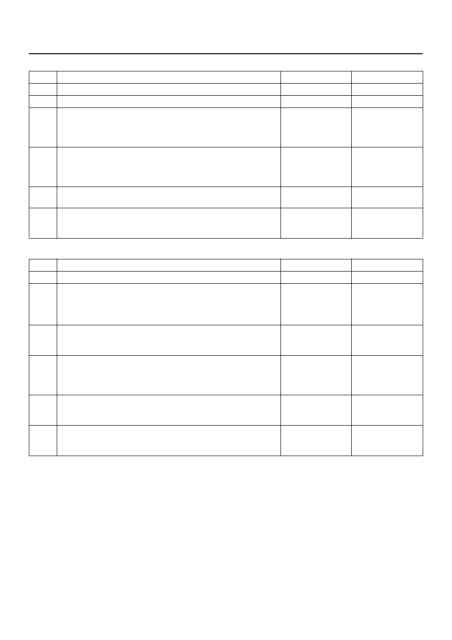
Chart A-3, TA-3 The Wheels Are Locked

Chart A-4 Brake Pedal Feed Is Abnormal

Step

Action

Yes

No

Is ABS working?

Go to Step 2

Go to Step 4

Is vehicle speed under 10 km/h (6mph)?

Go to Step 3

Normal.

Is sensor output normal? (Chart C-1 or TC-1)

Go to Step 4

Replace sensor 

or repair 

harness.

Go to Step 6

Is front 4WD controller normal?

Go to Step 5

Replace 4WD 

controller or 

repair harness.

Go to Step 6

Is hydraulic unit grounded properly?

Replace EHCU.

Go to Step 6

Repair.

Go to Step 6

Reconnect all components, ensure all components are properly
mounted.
Was this step finished?

Repeat the “Basic 

diagnostic flow 

chart”

Go to Step 6

Step

Action

Yes

No

Is the stop light actuated when the brake pedal is depressed?

Go to Step 2

Go to Step 3

1. Turn the ignition switch off.

2. Disconnected EHCU connector.

Is the check voltage EHCU connector terminals 13 to 7 when
brake pedal is depressed than battery voltage?

Go to Step 4

Harness NG 

between brake 

SW and EHCU.

Go to Step 6

Is stop light fuse normal?

Go to Step 5

Replace stop 

light fuse.

Go to Step 6

Is the check continuity between EHCU connector terminals, 7 to
body grounded?

Go to Step 6

Repair body 

grounded 

harness.

Go to Step 6

Is brake SW normal?

Repair stop 

light harness.

Go to Step 6

Replace brake 

SW.

Go to Step 6

Reconnect all components, ensure all components are properly
mounted.
Was this step finished?

Repeat the “Basic 

diagnostic flow 

chart”

Go to Step 6

5A–34

BRAKE CONTROL SYSTEM

Chart A-5, TA-5 Braking Sound (From EHCU) Is Heard While Not Braking

Step

Action

Yes

No

Is this the first vehicle start after engine start?

Normal.

(It is self 

checking 

sound.)

Go to Step 2

Is vehicle speed under 10 km/h (6 mph)?

Normal.

(It is self 

checking 

sound.)

Go to Step 3

Check for the following condition:

• At the time of shift down or clutch operation.

• At the time of low road friction drive (ice or snow road) or rough

road drive.

• At the time of high-speed turn.

• At the time of passing curb.

• At the time of operating electrical equipment switches.

• At the time of racing the engine (over 5000 rpm).
Did it occur under any one condition above?

ABS may 

sometimes be 
actuated even 

when brake pedal 

is not applied.

Go to Step 4

Is there play in each or any sensor/wheel speed sensor rings?

Repair.

Go to Step 7

Go to Step 5

Damage or powdered iron sticking to each or any sensor/wheel
speed sensor ring?

Repair.

Go to Step 7

Go to Step 6 

Is each sensor output normal? (Refer to chart C-1 or TC-1).

Check harness/ 

connector for 

suspected 

disconnection

If no 

disconnection is 

found, replace 

Coil integrated 

module.

Go to Step 7

Repair.

Go to Step 7

Reconnect all components, ensure all components are properly
mounted.
Was this step finished?

Repeat the “Basic 

diagnostic flow 

chart”

Go to Step 7

BRAKE CONTROL SYSTEM

5A–35

Diagnostic Trouble Codes

Choose and trace an appropriate flowchart by the
numbers listed below to find fault and repair.

Code

Diagnosis

Item

Chart 

No.

Flash out

Serial 

Communications

12

13

C0285

2 WD Controller in 4WD Vehicle Controller

Wiring

B-8

14

C0271

RAM read/write error

Coil Integrated 

Module

B-2

C0272

ROM checksum error

C0270

ALU function error

C0273

Inoperative isolation item

C0284

Loop time overrun

15

C0277

Low ignition voltage

Wiring

B-3

C0278

High ignition voltage

17

C0269

Excessive dump time

Coil Integrated 

Module

B-4

18

C0274

Excessive isolation time

B-5

21

C0276

G-Sensor Failure

B-6

22

C0281

Brake switch Failure

B-7

24

C0282

Open or shorted 4

´4 input signal (4WD only)

Wiring

B-8

32

C0267

Open motor circuit or shorted ECU output

Motor

B-9

C0268

Stalled motor or open ECU output

35

C0265

Open relay circuit

Relay

B-10

C0266

Shorted relay circuit

41

C0245

FL Open isolation solenoid or shorted ECU output

Solenoid

B-11

C0247

FL Shorted isolation solenoid or open ECU output

42

C0246

FL Open dump solenoid or shorted ECU output

B-12

C0248

FL Shorted dump solenoid or open ECU output

43

C0241

FR Open isolation solenoid or shorted ECU output

B-13

C0243

FR Shorted isolation solenoid or open ECU output

44

C0242

FR Open dump solenoid or shorted ECU output

B-14

C0244

FR Shorted dump solenoid or open ECU output

45

C0251

Rear Open isolation solenoid or shorted ECU output

B-15

C0253

Rear Shorted isolation solenoid or open ECU output

46

C0252

Rear Open dump solenoid or shorted ECU output

B-16

C0254

Rear Shorted dump solenoid or open ECU output

5A–36

BRAKE CONTROL SYSTEM

51

C0225

FL Open or shorted sensor

Sensor or 

Wiring

B-17

52

C0221

FR Open or shorted sensor

B-18

53

C0235

Rear Open or shorted sensor

B-19

61

C0226

FL Missing sensor signal

B-20

C0227

FL Sensor signal dropout

62

C0222

FR Missing sensor signal

B-21

C0223

FR Sensor signal dropout

63

C0236

Rear Missing sensor signal

B-22

C0237

Rear Sensor signal dropout

64

C0229

Simultaneous dropout of front sensor signal

B-23

65

C0238

Wheel speed error

Vehicle or 

Sensor

B-24

C0286

Shorted indicator lamp

Wiring

Code

Diagnosis

Item

Chart 

No.

Flash out

Serial 

Communications


Content   ..  1174  1175  1176  1177   ..