Isuzu Amigo / Axiom / Trooper / Rodeo / VehiCross. Manual - part 1177


  Index      Isuzu     Isuzu Amigo / Axiom / Trooper / Rodeo / VehiCross - service repair manual 1999-2002 year


Search            


Content   ..  1175  1176  1177  1178   ..


Isuzu Amigo / Axiom / Trooper / Rodeo / VehiCross. Manual - part 1177


BRAKE CONTROL SYSTEM

5A–37

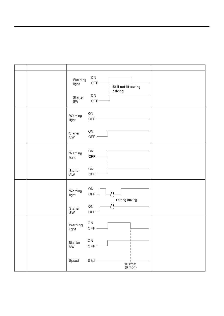
Diagnosis By “ABS”  Warning Light Illumination Pattern

In the event that there is abnormality in the “ABS”
warning light illumination pattern   while the key is in the
ON position or if the warning light is actuated while
driving, refer to the flow chart below for the correct
diagnostic procedure.

No.

Condition

“ABS” Warning Light Illumination Pattern

Diagnostic

1

Warning light is
actuated normally

Normal

2

Warning light is not lit

Warning  light  lighting  circuit
trouble

®Go to Chart B-1

3

Warning light remains
ON

Diagnostic trouble codes are
stored.
Display diagnostic trouble
codes and diagnose on a
code basis according to the
flow charts.

4

Warning light is
actuated while driving

Diagnostic trouble codes are
stored.
Display diagnostic trouble
codes and diagnose on a
code basis according to the
flow charts.

5

Warning light goes at
12 km/h (8 mph) or
higher (After repairing
the faulty part)

Even after repairing the faulty
part the warning light (W/L)
dose not go out if vehicle is at
a stop.
Turn the ignition switch to the
ON position and drive the
vehicle at 12 km/h (8 mph) or
higher to make sure that the
warning light goes out.

5A–38

BRAKE CONTROL SYSTEM

Diagnostic Trouble Codes (DTCs)

When the warning light in the meter remains ON, the
EHCU stores the fault identification and   disables the
ABS.
How to display and erase DTCs:

NOTE:

• DTCs can be displayed also by TECH 2. Use

“Diagnostic Trouble Codes” mode.

1. How to start DTC display:

• Confirm that the vehicle has come to a complete

stop (with the wheels standing still) and that the
brake   pedal is not depressed. (Unless these two
condition are satisfied, DTC display cannot be
started.)

• With IGN OFF, connect #12 terminal with #4

terminal or # 5 terminal (GND) . Then turn IGN
ON.

The DLC is located behind the driver side kick panel

350R100001

• Keep #12 terminal connected with #4 terminal or

# 5 terminal (GND) during DTC display.   (If #12
terminal is separated from #4 terminal or # 5
terminal (GND) during display, display will stop.)

2. DTC display:

• DTC is displayed by blinking warning light.

• Double-digit display.

• First, normal DTC 12 is displayed three times and

then any other DTCs are displayed three times.
(If no other DTCs have been stored, the display

of DTC 12 will be repeated.)

3. How to erase code:

• Conduct brake switch ON/OFF operation 6 or

more times within 3 seconds of   self-diagnosis
startup.

• The code cannot be erased if more than 3

seconds have passed since self-diagnosis
startup,   or if self-diagnosis has started with
brake switched on (brake pedaled).

B05RW005

BRAKE CONTROL SYSTEM

5A–39

4. Notes

• If the following should occur during Diagnostic

Trouble Code (DTC) display, the display will be
discontinued. After initial check, the status that is
under the control of ABS will be returned :

– The vehicle starts (The wheels turn) or the

brake pedal is depressed. 

• Up to 3 different codes can be stored. 

• If the ABS should turn OFF due to an intermittent

defect, the system will be restored at the next key
cycle,   if the initial check finds no abnormality
(when IGN is switched from OFF to ON).

5. An example of DTC display

B05R100001

After displaying DTC 12 three times, one DTC after
another is displayed, starting with the most recent
one. (However, display is discontinued after about 5
minutes.) 

B05R100002

The DTC 12 is displayed repeatedly. (display is
discontinued after about 5 minutes after) 

5A–40

BRAKE CONTROL SYSTEM

Chart B-1 With the key in the ON position (Before starting the engine).   Warning light (W/L)
is not activated.

Chart B-2 CPU Error (DTC 14 (Flash out) / C0271, C0272, C0273, C0284 (Serial
communications))

Step

Action

Yes

No

Is W/L fuse disconnected?

Replace fuse.

Go to Step 5

Go to Step 2

Is W/L burnt out?

Replace W/L 

bulb.

Go to Step 5

Go to Step 3

1. Turn the key off.

2. Disconnect coil integrated module connector (C-4).

3. Turn the key ON.

Is the check voltage between coil integrated module connector
(C-4) terminals 6 and 7 the battery voltage?

Go to Step 4

Repair harness 

and connector.

Go to Step 5

Is there the continuity between coil integrated module connector
(C-4) terminals, 1 and 7 and body ground.

Check harness 

for suspected 

disconnection

No fault found: 

Replace EHCU.

Go to Step 5

Repair harness 

and connector.

Go to Step 5

Reconnect all components, ensure all components are properly
mounted.
Was this step finished?

Repeat the “Basic 

diagnostic flow 

chart”

Go to Step 5

Step

Action

Yes

No

1. Turn the key off.

2. Disconnected coil integrated module connector.

3. Inspect coil integrated module ground.

Is there the continuity between the coil integrated module
connector terminals, 2 (C-5) and 7 (C-4) and body ground?

Go to Step 2

Repair the body 

ground 

harness.

Go to Step 3

1. Turn the key off, connect the coil integrated module

connector.

2. Erase the trouble code.

3. Turn Ignition off, then on, to perform system self-check.

4. If warning light remains on, display trouble codes once again.

Is the trouble code the DTC 14 (Flash out) / C0271, C0272,
C0273, C0284 (Serial communications)?

Replace EHCU.

Go to Step 3

Inspect in 

accordance with 

the DTC displayed.

1. Reconnect all components, ensure all components are

properly mounted.

2. Clear diagnostic trouble code.

Was this step finished?

Repeat the “Basic 

diagnostic flow 

chart”

Go to Step 3


Content   ..  1175  1176  1177  1178   ..