Isuzu Amigo / Axiom / Trooper / Rodeo / VehiCross. Manual - part 1164


  Index      Isuzu     Isuzu Amigo / Axiom / Trooper / Rodeo / VehiCross - service repair manual 1999-2002 year


Search            


Content   ..  1162  1163  1164  1165   ..


Isuzu Amigo / Axiom / Trooper / Rodeo / VehiCross. Manual - part 1164


TRANSFER CASE

4D–25

9. Remove needle bearing (8).

10. Remove bearing collar (9).

226RS071

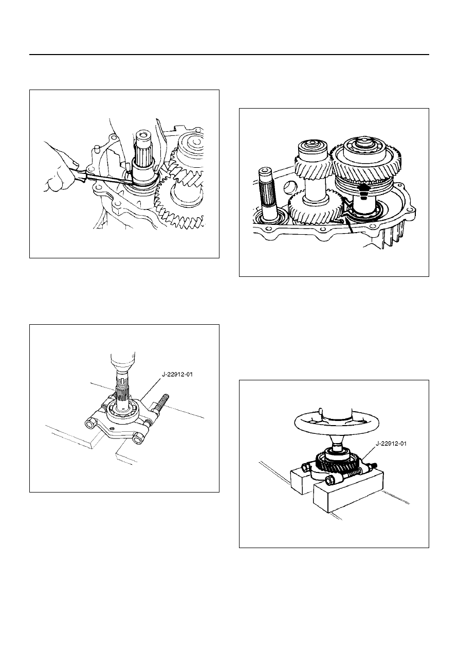
11. Remove ball (10).

12. Remove plate (11).

13. Use a bench press and the ball bearing remover J–

22912–01 to remove the ball bearing (12) from the
input shaft (13). (A/T)

265RS002

14. Use a pair of snap ring pliers to remove the bearing

snap ring (14).

15. Use a plastic hammer to tap the front output gear

assembly (15) free.

262RS009

16. Remove bearing snap ring (16).

17. Use a bench press and the bearing remover J–

22912–01 to remove the following parts.

18. Remove ball bearing (17), and bearing collar (18).

Remove sub–gear snap ring (19), spacer (20),
belleville spring (21), and sub–gear (anti–lash plate)
(22). (M/T)
Remove front output gear (23) and needle bearing
(24).

262RS010

19. Remove inside ring (25).

20. Remove outside ring (26).

21. Remove block ring (27).

4D–26

TRANSFER CASE

22. Use a bench press and bearing remover J–22912–

01 to remove 2WD–4WD clutch hub and sleeve
assembly (28) and stopper plate (29).

NOTE:  Do not reuse the stopper plate.

23. Disassemble the 2WD–4WD clutch hub and sleeve

assembly (28).

• Springs (1)

• Inserts (2)

• Clutch Hub (3)

• Sleeve (4)

226RW133

24. Use a bench press and the ball bearing remover J–

22912–01 to remove the ball bearing (30) from front
output shaft (31).

262RS011

25. Remove bearing snap ring (32).

26. Remove the counter gear assembly (33) from the

transfer case (42).

27. Use a pair of snap ring pliers to remove the snap

ring (34).

28. Use a bench press and the bearing remover J–

22912–01 to remove the ball bearing (35).

29. Use a pair of snap ring pliers to remove the snap

ring (36).

30. Use a bench press and the bearing remover J–

22912–01 to remove the ball bearing (37).

226RS073

31. Remove spacer (38).

32. Remove belleville spring (39).

33. Remove sub–gear (anti–lash plate) (40).

34. Remove counter gear (41).

35. Remove transfer case (with oil seal) (42),

performing the following steps  (M/T)

• Cover the shaft splines with adhesive tape (43).

A07RW022

EndOFCallout

Legend

(43) Adhesive Tape
(44) Oil Seal Lip
(45) Oil Seal Collar
(46) Bearing

TRANSFER CASE

4D–27

• Remove the transfer case together with

intermediate plate with gear assembly from the
transmission case (M/T).

• Remove the transfer case from the intermediate

plate with gear assembly (M/T).

Inspection and Repair

1. Make the necessary repair or parts replacement if

wear, damage or any other abnormal conditions are
found during inspection.

2. Wash all parts thoroughly in clean solvent. Be sure

all old lubricant, metallic particles, dirt, or foreign
material are  removed from the surfaces of every
part. Apply compressed air to each oil feed port and
channel in each case half to remove any
obstructions or cleaning solvent residue.

Gears

1. Inspect all the gear teeth for signs of excessive

wear or damage and check all the gear splines for
burrs, nicks, wear or damage. Remove the minor
nicks or scratches on an oil stone. Replace any part
exhibiting excessive wear or damage.

Front Output Gear Inside Diameter

1. Use an inside dial indicator to measure the gear

inside diameter.

2. If the measured value exceeds the specified limit,

the gear must be replaced.

Gear inside diameter

Standard : 48.000–48.013 mm (1.8898–1.8903 in)

Limit : 48.10 mm (1.894 in)

226RS040

Clutch Hub Spline Play

1. Set a dial indicator to the clutch hub to be

measured.

2. Move the clutch hub as far as possible to both the

right and the left.
Note the dial indicator reading.

3. If the measured value exceeds the specified limit,

the clutch hub must be replaced.

Clutch hub spline play

Standard : 0–0.1 mm (0–0.004 in)

Limit : 0.2 mm (0.008 in)

226RS042

Bearings

1. Inspect the condition of all the needles and ball

bearings. Wash bearings thoroughly in a cleaning
solvent. Apply compressed air to the bearings.

NOTE:  Do not allow the bearings to spin. Turn them
slowly by hand. Spinning bearings may damage the
rollers.

2. Lubricate the bearings with a light oil and check

them for roughness by slowly turning the race by
hand.

Ball Bearing Play

1. Use a dial indicator to measure the ball bearing play.

2. If the measured value exceeds the specified limit,

the ball bearing must be replaced.

Limit : 0.2 mm (0.008 in)

226RS043

4D–28

TRANSFER CASE

Synchronizers

The synchronizer hubs and sliding sleeves are a
selected assembly and should be kept together as
originally assembled.
Clean synchronizer components with clean solvent and
air dry.
Inspect the components for the following:

• Teeth for wear, scuffs, nicks, burrs or breaks.

• Keys and springs for wear, cracks or distortion,

replace if these conditions are present.

• If scuffed, nicked or burred conditions cannot be

corrected with a soft stone or crocus cloth, replace
the component.

Block Ring and Insert Clearance

1. Use a vernier caliper to measure the clearance

between the block ring and the insert.

2. If the measured value exceeds the specified limit,

the block ring and the insert must be replaced.

Block ring and insert clearance

Standard : 2.46–2.74 mm (0.097–0.108 in)

Limit : 3.0 mm (0.118 in)

226RS037

2WD–4WD Synchronizer (3–Cone)

1. Use a thickness gauge to measure the clearance

between the block ring and the dog teeth.

2. If the measured value exceeds the specified limit,

the 2WD–4WD synchronizer assembly must be
replaced.

Block ring and insert clearance

Standard : 1.5 mm (0.059 in)

Limit : 0.8 mm (0.031 in)

226RW142

Clutch Hub and Insert Clearance

1. Use a thickness gauge to measure the clearance

between the clutch hub and the insert.

2. If the measured value exceeds the specified limit,

the clutch hub and the insert must be replaced.

Clutch hub and insert clearance

Standard : 0.01–0.19 mm (0.0004–0.0075 in)

Limit : 0.3 mm (0.012 in)

226RS038


Content   ..  1162  1163  1164  1165   ..