Isuzu Amigo / Axiom / Trooper / Rodeo / VehiCross. Manual - part 1163


  Index      Isuzu     Isuzu Amigo / Axiom / Trooper / Rodeo / VehiCross - service repair manual 1999-2002 year


Search            


Content   ..  1161  1162  1163  1164   ..


Isuzu Amigo / Axiom / Trooper / Rodeo / VehiCross. Manual - part 1163


TRANSFER CASE

4D–21

Inspection and Repair

Refer to 

Transfer Case Assembly in this section for

inspection and repair.

Reassembly

1. Place shift block (15) in transfer case (16).

2. Set shift arm (14) on the High–Low sleeve.

3. Push High–Low shift rod (13) through shift arm (14)

and block (14).

4. Engage the High–Low sleeve with the 4H (1) side.

5. Install the spring pin (12) to the shift block (15) and

shift arm (14).

262RW034

6. Install select rod assembly (11), joining its lever to

shift block groove.

7. Engage the High–Low sleeve with the 4H side and

install the interlock pin and spring (10) in the proper
direction.

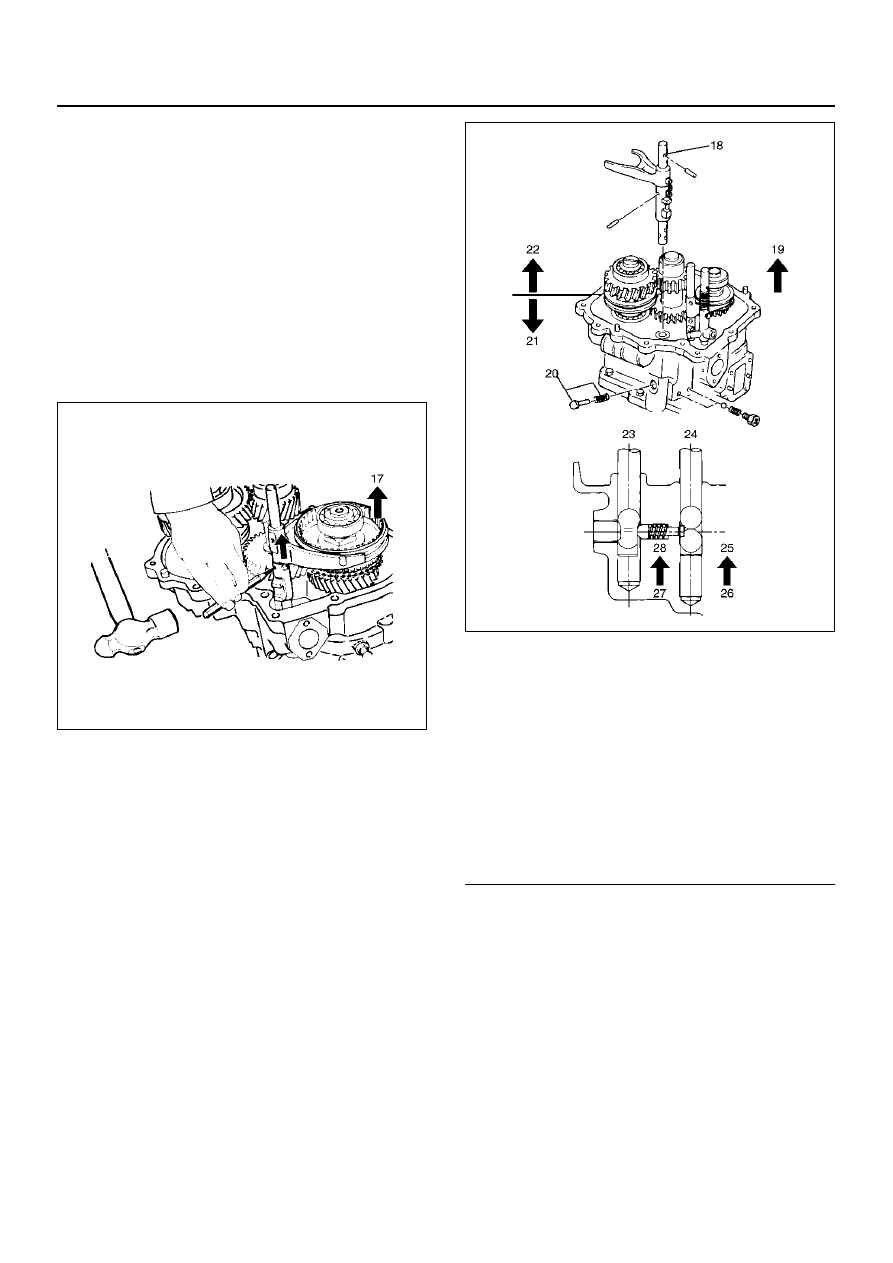
8. Place 2WD–4WD shift block in the transfer case

(16).

9. Set 2WD–4WD shift arm on the 2WD–4WD sleeve.

10. Puh 2WD–4WD shift rod through 2WD–4WD shift

arm and 2WD–4WD shift block.

11. Install the shift rod: 2WD–4WD (5) with interlock pin

pushed in.

262RW035

EndOFCallout

12. Install 4WD indicator switch and gasket (8).

Tighten to the specified torque.

Torque: 39 N·m (29 lb ft)

13. Install spring (4).

Legend

(18) 2WD–4WD
(19) 4H Side
(20) Interlock pin
(21) 2WD
(22) 4WD
(23) Rod: 2–4
(24) Rod: H–L
(25) 4H
(26) 4L
(27) 4

´2

(28) 4

´4

4D–22

TRANSFER CASE

14. Engage the 2WD–4WD sleeve with the 4WD side

and install the spring pin (3).

262RW022

15. Install spring pin (2) and bridge (2).

16. Install detent ball, spring, gasket and plug and

tighten the plug to the specified torque.

Torque: 25 N·m (18 lb ft)

TRANSFER CASE

4D–23

Transfer Case Assembly

Disassembled View

226RW209

Legend

(1) Bearing Snap Ring
(2) Ball Bearing
(3) Lock Nut
(4) Snap Ring (A/T)
(5) Input Shaft Assembly (A/T)
(6) High–Low Clutch Hub and Sleeve
(7) Transfer Input Gear
(8) Needle Bearing
(9) Bearing Collar

(10) Ball

(11) Plate

(12) Ball Bearing (A/T)
(13) Input Shaft (A/T)
(14) Bearing Snap Ring
(15) Front Output Gear Assembly

(16) Bearing Snap Ring
(17) Ball Bearing
(18) Bearing Collar
(19) Sub–Gear Snap Ring (M/T)
(20) Spacer (M/T)
(21) Belleville Spring (M/T)
(22) Sub–Gear (anti–lash plate) (M/T)
(23) Front Output Gear
(24) Needle Bearing
(25) Inside Ring
(26) Outside Ring
(27) Block Ring
(28) 2WD–4WD Clutch Hub and Sleeve Assembly
(29) Stopper Plate
(30) Ball Bearing
(31) Front Output Shaft

4D–24

TRANSFER CASE

EndOFCallout

Disassembly

1. Use a pair of snap ring pliers to remove the snap

ring (1).

2. Use a bearing remover J–37217 and puller J–37487

to remove the ball bearing (2).

262RW016

3. Install the front companion flange temporarily.

4. Use the Companion flange holder J–8614–11 and

lock nut wrench J–37219 to remove the lock nut (3).

226RX001

5. Remove the front companion flange.

6. Remove snap ring (4). (A/T)

7. Remove the input shaft assembly (5) from the

transfer case (42). (A/T)

265RW001

8. Use the universal puller to remove the high–low

clutch hub and sleeve (6), and transfer input gear
(7).

226RS070

(32) Bearing Snap Ring
(33) Counter Gear Assembly
(34) Snap Ring
(35) Ball Bearing
(36) Snap Ring
(37) Ball Bearing

(38) Spacer
(39) Belleville Spring
(40) Sub–Gear (anti–lash plate)
(41) Counter Gear
(42) Transfer Case (with oil seal)


Content   ..  1161  1162  1163  1164   ..