Isuzu Amigo / Axiom / Trooper / Rodeo / VehiCross. Manual - part 1130


  Index      Isuzu     Isuzu Amigo / Axiom / Trooper / Rodeo / VehiCross - service repair manual 1999-2002 year


Search            


Content   ..  1128  1129  1130  1131   ..


Isuzu Amigo / Axiom / Trooper / Rodeo / VehiCross. Manual - part 1130


4A1–14

DIFFERENTIAL (FRONT)

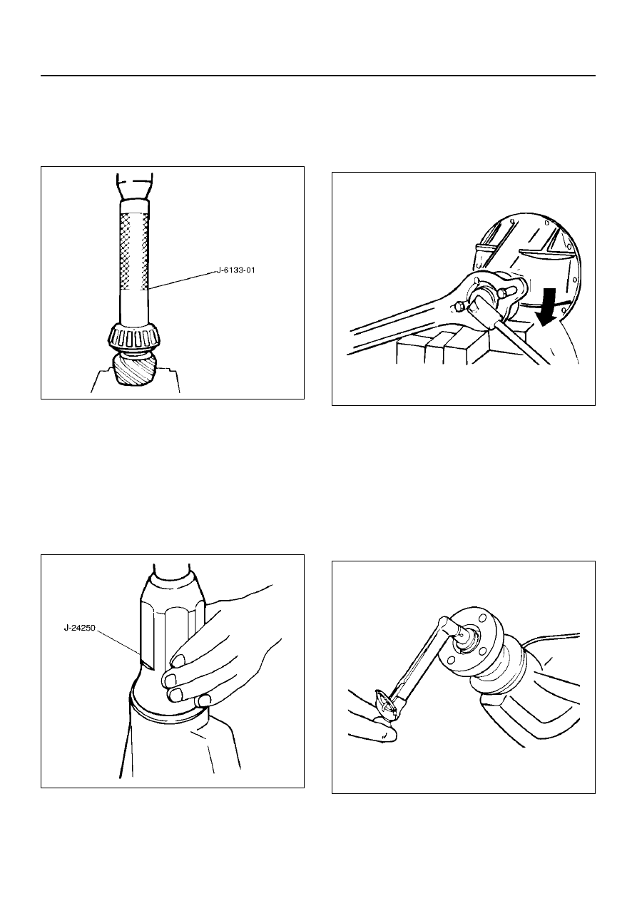
4. Place the shim on the drive pinion. Install the inner

bearing onto the pinion using an installer J–6133–01
and a press.

NOTE:  Do not apply pressure to the roller cage and
apply pressure only to the inner race.

425RW036

5. Discard the used collapsible spacer and install a

new one.

6. Install pinion gear.

7. Install outer bearing.

8. Install oil seal slinger.

9. Use oil seal installer J–24250 to install a new oil

seal that has been soaked in front axle lubricant.

NOTE:  Take care to use a front differential oil seal,
NOT the rear differential oil seal.

415RS011

10. Install flange.

11. Install flange nut.

1. Apply lubricant to the pinion threads.

2. Tighten the nut to the specified torque using the

pinion flange holder J–8614–01.

Torque: 217N·m (160lb ft)

NOTE:  Discard used flange nut and install new one and
do not over tighten the flange nut.

415RW006

3. Adjust pinion bearing preload.

a

Measure the bearing preload by using a
torque meter. Note the scale reading
required to rotate the flange.

b

Continue tightening flange nut until the
specified starting torque is obtained.

Starting torque:0.6–1.1 N·m(5.6–10.0 lb in)

NOTE:  Do not tighten the flange nut more than
678 N·m(500lb ft).

425RW018

DIFFERENTIAL (FRONT)

4A1–15

12. Install adjust shim.

1. Attach the side bearing to the differential

assembly without shims. Support the opposite
side using a pilot to prevent bearing damage.

425RS029

EndOFCallout

2. Insert the differential cage assembly with

bearing outer races into the side bearing bores
of the carrier.

425RS030

3. Using two sets of feeler gauges, insert a feeler

stock of sufficient thickness between each
bearing outer race and the carrier to remove all
end play. Make certain the feeler stock is
pushed to the bottom of the bearing bores.
Mount the dial indicator J–8001 on the carrier so
that the indicator stem is at right angles to a
tooth on the ring gear.

425RS031

4. Adjust feeler gauge thickness from side to side

until ring gear backlash is in the specified range.

Backlash: 0.13–0.20mm(0.005 –0.008 in)

425RS032

With zero end play and correct backlash
established, remove the feeler gauge packs,
determine the thickness of the shims required
and add 0.025 mm (0.001 in) to each shim pack
to provide side bearing preload. Always use new
shims.

Legend

(1) Drive handle:J–8092
(2) Installer:J–24244
(3) Pilot:J–8107–2

4A1–16

DIFFERENTIAL (FRONT)

5. Use bearing remover J–42379 and pilot J–

8107–2 to remove side bearing.

• Select insert; 303173 and collet halves;44801

in remover kit J–42379.

415RW003

13. Install the side bearings together with the selected

shims.

425RS029

EndOFCallout

14. Install side bearing outer race.

15. Install differential cage assembly.

16. Install bearing cap then align the setting marks(1)

applied at disassembly.

425RS035

17. Tighten the cap  bolt to the specified torque.

Torque: 97 N·m (72lb ft)

425RS036

Gear Tooth Contact Pattern Check and
Adjustment

1. Apply a thin coat of prussian blue or equivalent

to at least 7-8 ring gear teeth. Rotate the ring
gear and inspect the contact point of the
impressions and make the necessary
adjustments as   described in the next page. 

Legend

(1) Drive Handle:J–8092
(2) Installer: J–24244
(3) Pilot: J–8107–2

DIFFERENTIAL (FRONT)

4A1–17

425RS038

EndOFCallout

425RS039

Legend

(1) Heel
(2) Toe
(3) Concave Side(Coast)
(4) Convex Side(Drive)


Content   ..  1128  1129  1130  1131   ..