Isuzu Amigo / Axiom / Trooper / Rodeo / VehiCross. Manual - part 1128


  Index      Isuzu     Isuzu Amigo / Axiom / Trooper / Rodeo / VehiCross - service repair manual 1999-2002 year


Search            


Content   ..  1126  1127  1128  1129   ..


Isuzu Amigo / Axiom / Trooper / Rodeo / VehiCross. Manual - part 1128


4A1–6

DIFFERENTIAL (FRONT)

Removal

1. Jack up the vehicle and support it using jack stand.

2. Remove the tire and wheel.

3. Remove the stone guard.

4. Remove the brake caliper fixing bolt and hang the

caliper.  Refer to Disc Brakes in Brake section.

5.  Remove the antilock brake system speed sensor.

 Refer to Front Wheel Speed Sensor in Brake
section.

6.  Remove the hub and disc assembly.

 Refer to Front Hub and Disc in this section.

7. Remove the propeller shaft, refer to Front Propeller

Shaft in this section.

8. Loosen the height control arm of the torsion bar,

then remove the torsion bar from lower control arm.
refer to Torsion Bar in Suspension section.

9. Remove the suspension crossmember.

10. Remove the lower nut (1) of the stabilizer link.

11. Remove the lower bolt and nut (2) of the shock

absorber.

412RW057

12. Remove the tie-rod end from the knuckle.  Refer to

Power Steering Unit in Steering Section.

13. Disconnect the hose of the shift on the fly.

14. Disconnect the actuator connector.

15. Remove the bolts and nuts of the lower control arm

(Frame side), then disconnect the lower control arm
from frame.

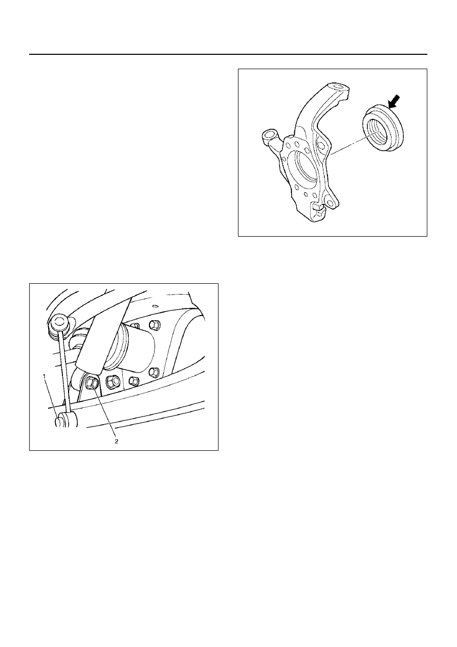
16. Disconnect between the right side upper control arm

and the knuckle, then remove the knuckle with lower
control arm.

CAUTION:  When removing the knuckle, be careful
not to damage the oil seal inside of the knuckle.

410R200003

17. Support the differential case by the jack.

18. Remove the front axle mounting bolts and nuts,

lower the jack slowly.  Remove the left side drive
shaft end from the knuckle, then lower the axle
assembly from the vehicle.

CAUTION:

1. Make sure the axle assembly is supported

securely when performing repairs. 

2. Do not damage the power steering unit when

performing the repairs. 

3. Do not damage the shift-on-the fly hose bracket

when performing the repairs. 

Installation

1. Support the differential case with a jack.

2. Jack up the front drive axle assembly, install the left

side drive shaft to the knuckle, then install the mount
bolts and nuts.

CAUTION:

1. Do not damage the power steering unit when

performing the repairs. 

2. Do not damage the shift-on-the fly hose bracket

when performing the repairs. 

3. When installing the drive shaft to the knuckle,

be careful not to damage the oil seal inside of
the knuckle.

DIFFERENTIAL (FRONT)

4A1–7

3. Tighten the mounting bolts and nuts to the specified

torque.

Torque:168 N·m (124 lb ft)

412RW064

4. Install the right side knuckle with lower control arm

to the upper control arm.
Refer to Knuckle in Suspension section.

CAUTION:  Carefully insert the drive shaft into the
knuckle, to avoid damaging the oil seal. 

5. Align the bolt hole of the lower control arm, then

install the bolts and nuts.

NOTE:  Adjust the buffer clearance before tightening
the bolts and nuts of the lower control arm.

6. Install the hose of the shift on the fly.

7. Install the actuator connector of the shift on the fly.

8. Install the tie-rod end of the power steering unit to

the knuckle, tighten the nut to the specified torque.

Torque:118N·m (87 lb ft)

9. Install lower bolts and nuts of the shock absorber,

tighten it to the specified torque.

Torque:93 N·m (69 lb ft)

10. Install lower nuts of the stabilizer link, tighten it to

the specified torque.

11. Install the suspension crossmember.

12. Install the torsion bar.

Refer to Torsion Bar in Suspension section.

13. Install the front propeller shaft.

Refer to Front Propeller Shaft in this section.

14. Install the hub and disc assembly and adjust the

bearing preload.
Refer to Front Hub and Disc in this section.

15. Install the wheel speed sensor of the antilock brake

system.

16. Install the brake caliper.  Tighten the bolt of the

caliper bracket to the specified torque.

Torque: 50 N·m (37 lb ft)

17. Install the stone guard.

18. Install the tire and wheel.

19. Lower the vehicle, adjust the trim height.

Refer to Trim Height Adjustment in Steering section.

20. Tighten the bolts and nuts of the lower control arm

to the specified torque.
Refer to Lower Control Arm in Suspension section.

4A1–8

DIFFERENTIAL (FRONT)

Differential Assembly

Disassembled View

415RY00008

EndOFCallout

Legend

(1) Differential Assembly
(2) Flange Nut
(3) Flange
(4) Oil Seal
(5) Oil Seal Slinger
(6) Outer Bearing 
(7) Outer Bearing Outer Race
(8) Differential Carrier
(9) Bearing Cap

(10) Bolt

(11) Collapsible Spacer

(12) Inner Bearing Outer Race
(13) Inner Bearing
(14) Adjust Shim
(15) Pinion Gear
(16) Diff Cage Assembly
(17) Side Bearing Outer Race
(18) Side Bearing
(19) Adjust Shim
(20) Bolt
(21) Axle Case

DIFFERENTIAL (FRONT)

4A1–9

Disassembly

1. Remove differential carrier fixing bolt.

2. Remove differential assembly.

3. Using holding fixture J–37264 and holding fixture

base J–3289–20, fix the differential assembly to the
bench.

425RS008

4. Remove bearing cap bolt.

5. Apply a setting mark to the side bearing cap and the

differential carrier then remove bearing cap.

425RS009

6. Remove differential cage assembly.

7. Remove side bearing outer race, after removal,

keep the right and left hand side bearing assemblies
separate to maintain inner and outer race
combinations.

8. Remove side bearing, using remover J–42379 and

adapter J–8107–2.

• Select insert; 303173 and collet halves; 44801 in

remover kit J–42379.

415RW003

9. Remove adjust shim, note the thickness and

position of the shims removed.

10. Remove the flange nut using holding wrench J–

8614–01.

415RS018


Content   ..  1126  1127  1128  1129   ..